Unfortunately, this is not readily deducible from the records of a particular operator, even if they are accurate.
Specifically, loss is proportionally greater in smaller gauge cables.
While these effects are not important with voice signals, these effects are considerable in relation to higher frequency transmissions because the associated error in the determination can yield misleading results.
For example, in the UK, the average scaling factor is probably somewhere between 1.4 and 2.0; the resulting distances are often enough to render a link unsuitable for the provision of
wideband or
broadband services, while the uncertainty in ascertaining actual cable
route lengths makes this method highly inaccurate.
Of course, there are other factors that contribute to attenuation or loss, but these are of relatively minor importance and deserve just a passing note, namely loss caused within the
dielectric between copper pairs and impedance mismatch at discontinuities, such as at joints between cabling sections.
This is a
time consuming and consequently expensive solution, especially if the customer decides not to take the service, or takes it only for a short period.
Equally this latter method gives no indication of the length and performance of the copper drops from the cabinet into a customer's premises.
This method is, therefore, again rather inaccurate.
Unfortunately, this method is not conducive to copper pairs since there can be many reflections from imperfections, spliced joints, etc., which may
mask the ultimate reflection, if any, from the end of the cable.
Also, although most telephones are quite well matched to the line in the voice band (when they are on-hook), they may not produce a reflection at a TDR impulse at the point where it may be most useful; in off-hook scenarios telephones are not matched to the line and will have erratic reflection coefficients.
Equally, the number of telephones connected at a customer's premises, and hence the differing impedance produced, could cause spurious results.
The main difficulty is that TDR measurements require a
fast pulse to operate accurately.
This is not possible with copper cables beyond a few hundred metres in length, since the reflected
signal will be lost in
background noise.
Again, therefore, this method is not appropriate.
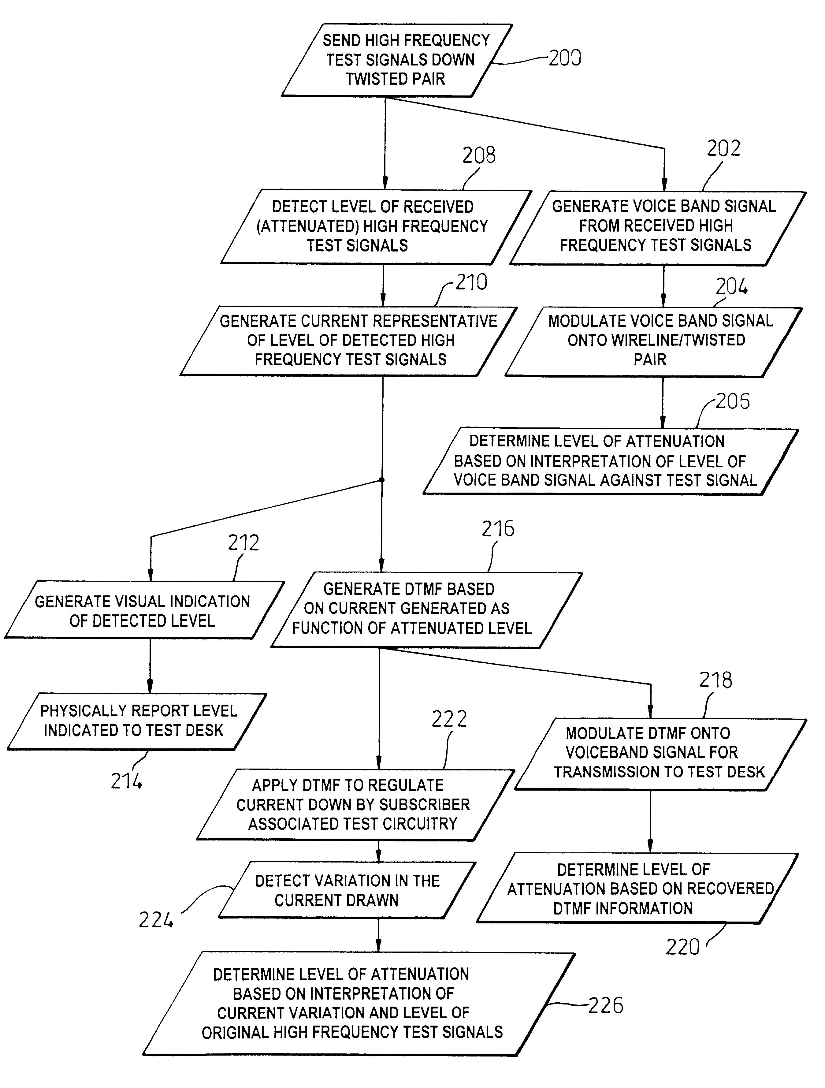
However, the use of standardised
telephony tones emanating from a subscriber terminal is not ideal since such
telephony tones are presently only defined within a predetermined but relatively wide tolerance, while the test tones are also (usually) transmitted in the voice band (which is unrelated to the spectrum of interest).
Consequently, some error exists in any
quantitative assessment at the exchange because of the uncertainty present in the absolute transmitted level, with this basic method also requiring the potential subscriber having access to a DTMF keypad.
As such, an
absolute level of attenuation caused by the wireline cannot be assessed, especially for high frequencies.
However, a drawback with this method is that there is still some uncertainty associated with a level of a transmitted test
signal.
In other words, the operator is unable to advise all its available clients of the possibility to
upgrade their respective services, which immediately inhibits its ability both to encourage subscription to the
enhanced service and to optimise its revenue.



