Lithographic imaging with metal-based, non-ablative wet printing members

a technology of metal-based and non-ablative wet printing, applied in the direction of foil printing, plate printing, duplication/marking methods, etc., can solve the problems of ordinarily impossible image, impossible to image, etc., and achieve the effect of simple construction

Inactive Publication Date: 2002-04-30
MARK ANDY
View PDF16 Cites 18 Cited by
  • Summary
  • Abstract
  • Description
  • Claims
  • Application Information

AI Technical Summary

Benefits of technology

The present invention obviates the need for substantial ablation as an imaging mechanism, combining the benefits of simple construction, the ability to utilize traditional metal base supports, and amenability to imaging with low-power lasers that need not impart ablation-inducing energy levels. In preferred embodiments, the invention utilizes a printing member having a topmost layer that is ink-receptive and a hydrophilic metal substrate. The topmost layer does not significantly

Problems solved by technology

It must be stressed that it is ordinarily impractical or even impossible to image, by ab

Method used


Image

  • Lithographic imaging with metal-based, non-ablative wet printing members
  • Lithographic imaging with metal-based, non-ablative wet printing members
  • Lithographic imaging with metal-based, non-ablative wet printing members

Examples


example 5

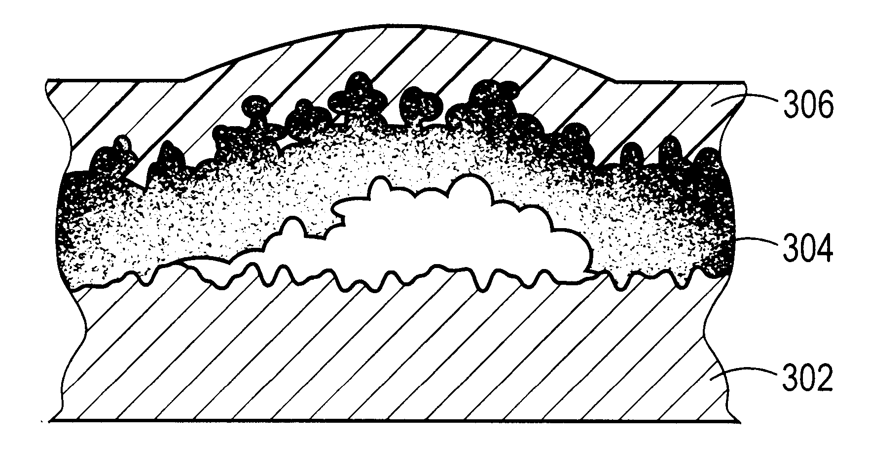
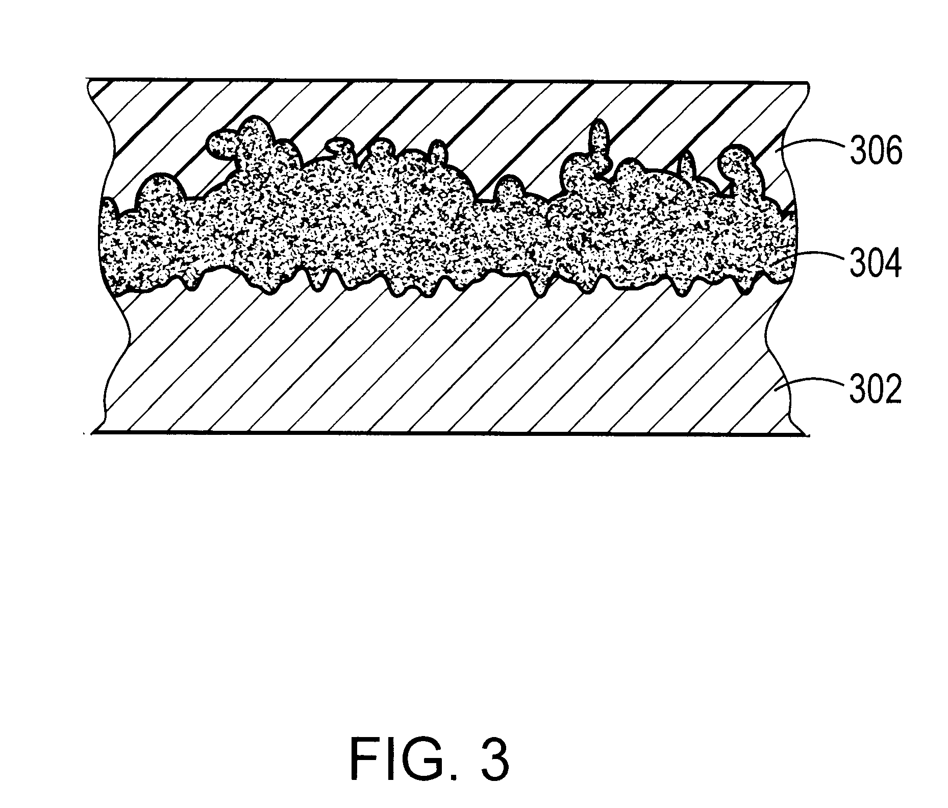
is optimal for coating over uniform layer 304 as described in Example 4. Cast and cured on this layer 304 or that described in Examples 1 / 3, the result is a black image on a light gray background (the color of the lithographic aluminum substrate 302). It is found that the layer 304 of Example 5 does not interact well with the dye-based construction of Examples 2 / 3. Example 6 may be cast and cured on layer 304 in accordance with Examples 1 / 3, but produces a light olive green image on a light gray background that may be difficult to assess for quality. Example 7, however, cast and cured on the formulation of Examples 1 / 3 provides a bright blue image easily distinguished over a gray background.

Numerous variations on these approaches are possible. For example, using lithographic aluminum as substrate 302, it is possible to apply, dry and cure a polyvinyl alcohol / BACOTE 20 coating containing NACURE 2530. The result is a hydrophilic coating containing free PTSA (p-toluene sulfonic acid); ...


PUM

PropertyMeasurementUnit
Thicknessaaaaaaaaaa
Concentrationaaaaaaaaaa
Electrical conductoraaaaaaaaaa

Abstract

Lithographic imaging using non-ablative printing members combines the benefits of simple construction, the ability to utilize traditional metal base supports, and amenability to imaging with low-power lasers that need not impart ablation-inducing energy levels. A representative printing member has a hydrophilic metal substrate and, thereover, first and second layers. The first layer has a thickness and an exposure surface and comprises a material that absorbs imaging radiation. The second layer overlies the first layer and is oleophilic and substantially transparent to imaging radiation. Exposure to imaging radiation causes the first layer and the substrate to irreversibly detach without substantial ablation, thereby facilitating removal, by subjection to the cleaning liquid, of the first and second layers where detachment has taken place.

Description

The present invention relates to digital printing apparatus and methods, and more particularly to imaging of lithographic printing-plate constructions on- or off- press using digitally controlled laser output.In offset lithography, a printable image is present on a printing member as a pattern of ink-accepting (oleophilic) and ink-rejecting (oleophobic) surface areas. Once applied to these areas, ink can be efficiently transferred to a recording medium in the imagewise pattern with substantial fidelity. Dry printing systems utilize printing members whose ink-repellent portions are sufficiently phobic to ink as to permit its direct application. Ink applied uniformly to the printing member is transferred to the recording medium only in the imagewise pattern. Typically, the printing member first makes contact with a compliant intermediate surface called a blanket cylinder which, in turn, applies the image to the paper or other recording medium. In typical sheet-fed press systems, the r...

Claims


Application Information

Patent Timeline
IPC IPC(8): B41C1/10B41C1/055B41N1/14
CPCB41C1/1016B41C2210/24B41C2210/02B41C2201/02B41C1/10
Inventor LEWIS, THOMAS E.
Owner MARK ANDY
Why Eureka
Try Eureka