Exhaust temperature raising apparatus and method for internal combustion engine

a technology of exhaust temperature and raising apparatus, which is applied in mechanical equipment, electric control, machines/engines, etc., can solve the problems of catalyst not being able to sufficiently control the emission of catalysts, unable to reduce unburned hcs, and large amounts of diesel engines

Inactive Publication Date: 2002-05-07
TOYOTA JIDOSHA KK
View PDF24 Cites 42 Cited by
  • Summary
  • Abstract
  • Description
  • Claims
  • Application Information

AI Technical Summary

Problems solved by technology

Diesel engines produce large amounts of unburned HCs during low-load engine operations, and particularly during a warm-up operation, since the combustion chamber temperature is low during such operations.
However, unless activated, the catalyst is unable to sufficiently control emission, that is, unable to lessen unburned HCs.
Furthermore, since unburned HCs produced by the main combustion burn together with the sub-injection fuel, the amount of combustion increases.
Although various technologies for lessening unburned HCs have been proposed, further reduction of the amount unburned HCs is still raised as a great issue.
It is conceivable that a failure in any one of the sensors can adversely affect the exhaust gas temperature.
If such a sensor fails, the exhaust gas temperature cannot be monitored, so that the exhaust gas temperature control becomes impossible.
As a result, the exhaust gas temperature does not remain in a temperature range of a target level (hereinafter, referred to as "target exhaust gas temperature"), so that production of unburned HCs may not be curbed.
Furthermore, due to a failure or defect in a fuel injection valve or a fuel injection valve control apparatus, as for example, a sufficient amount of fuel may not be injected, and therefore the exhaust gas temperature may not reach the target exhaust gas temperature, or the amount of fuel injected may be excessively large, and therefore the exhaust gas temperature may exceed the target exhaust gas temperature.
Therefore, the catalyst may deteriorate due to overheating, or the amount of HCs produced may increase more than necessary.
At the time of the stop, therefore, undesired excessive combustion in the cylinder discontinues.

Method used


Image

  • Exhaust temperature raising apparatus and method for internal combustion engine
  • Exhaust temperature raising apparatus and method for internal combustion engine
  • Exhaust temperature raising apparatus and method for internal combustion engine

Examples


first embodiment

the invention will be described with reference to FIGS. 1 and 2.

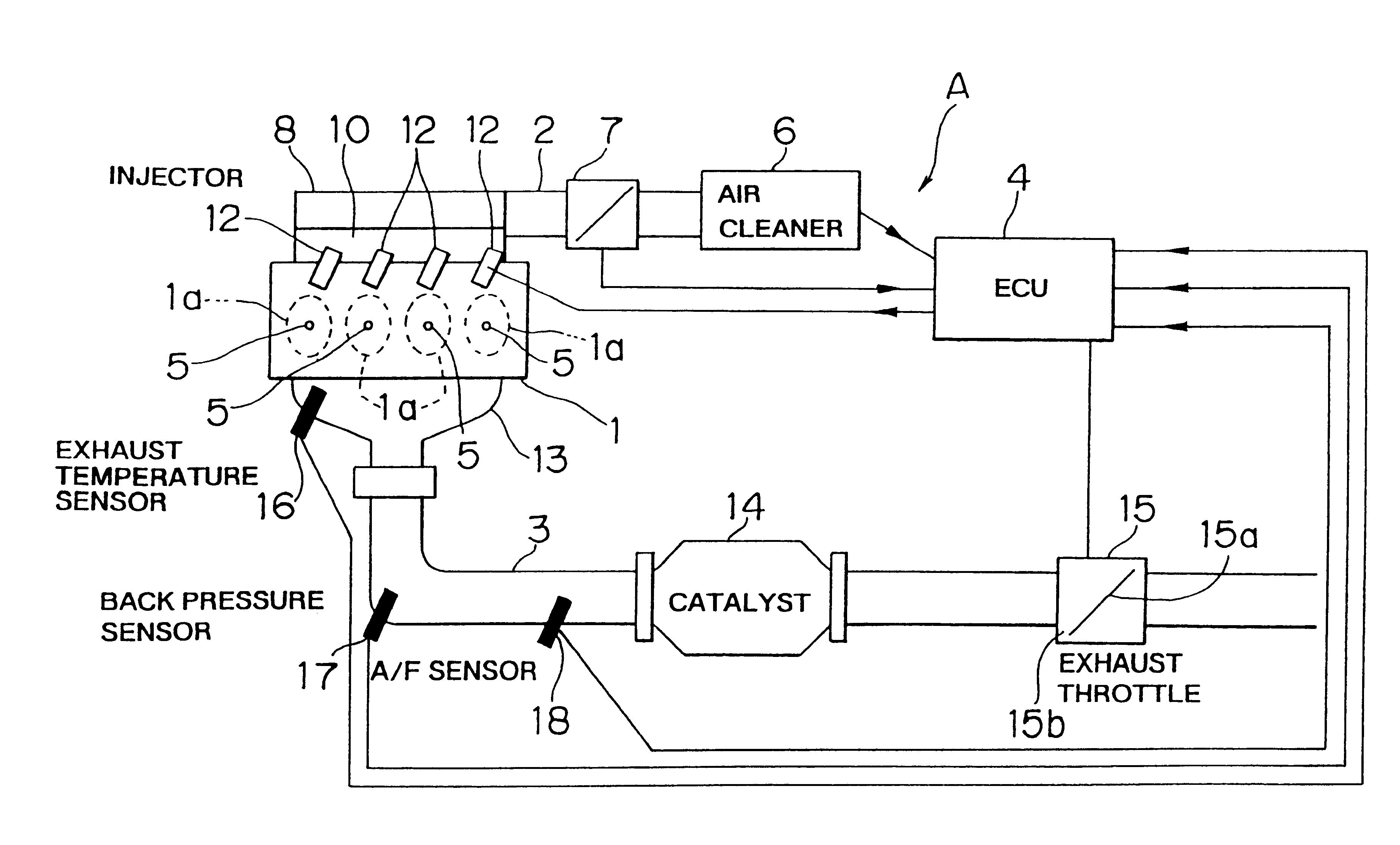
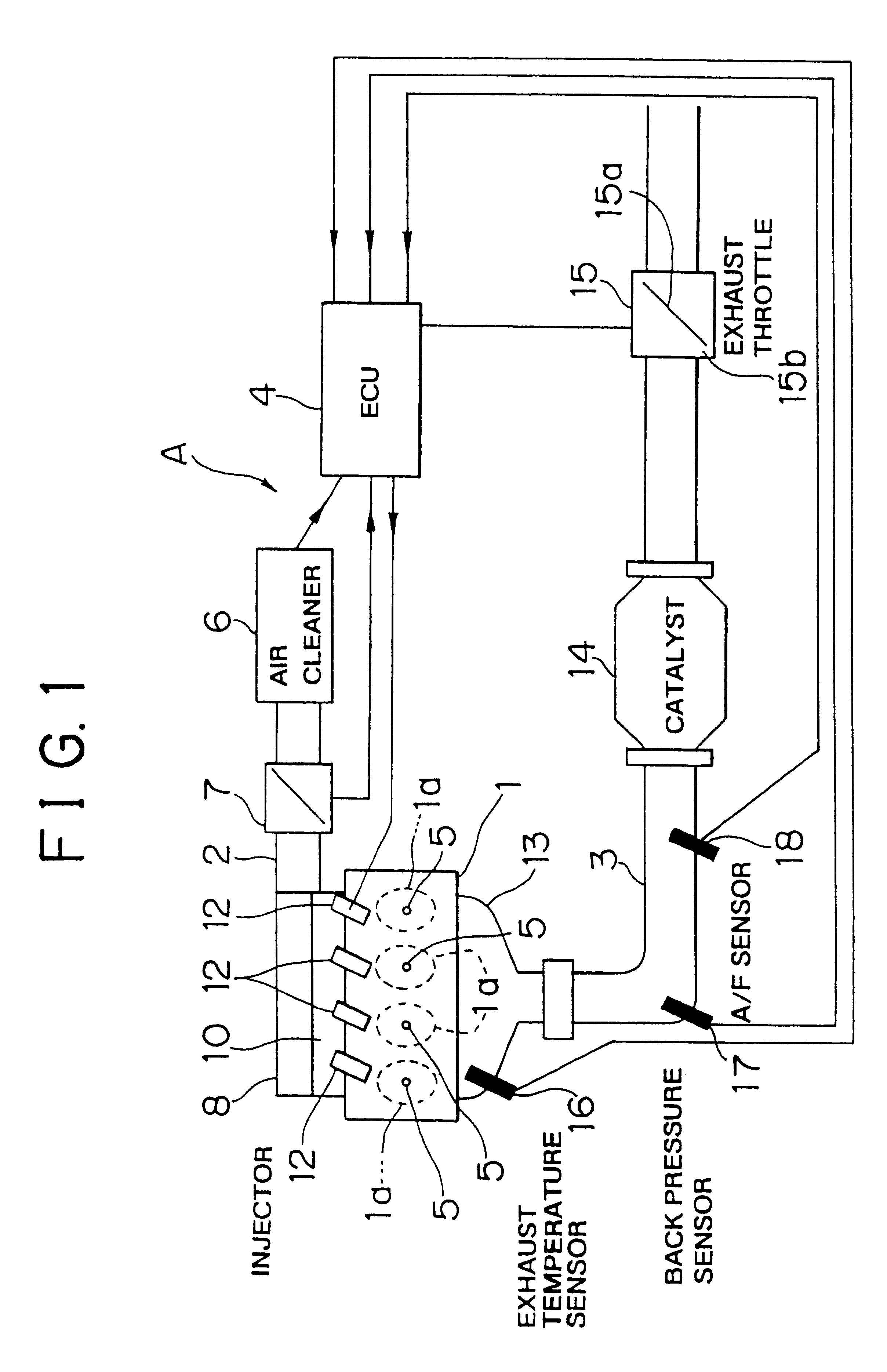
FIG. 1 is a schematic illustration of a lean-burn engine A (hereinafter, referred to as "engine A") that includes an internal combustion engine exhaust temperature raising apparatus according to the invention.

The engine A is a four-cylinder four-stroke engine having a cylinder block 1 in which four cylinders 1a are formed. Each cylinder 1a has a combustion chamber (not shown) to which an intake passage 2 and an exhaust passage 3 are connected in communication. The operation of the engine A is controlled by an ECU 4 that is an engine control unit.

The cylinder block 1 is provided with ignition plugs 5 corresponding to the individual cylinders 1a.

Each ignition plug 5 performs ignition based on an ignition signal distributed by a distributor (not shown).

The distributor distributes a high voltage outputted from an igniter to each ignition plug 5 synchronously with the crank angle of the engine A. The distributor and the igni...

second embodiment

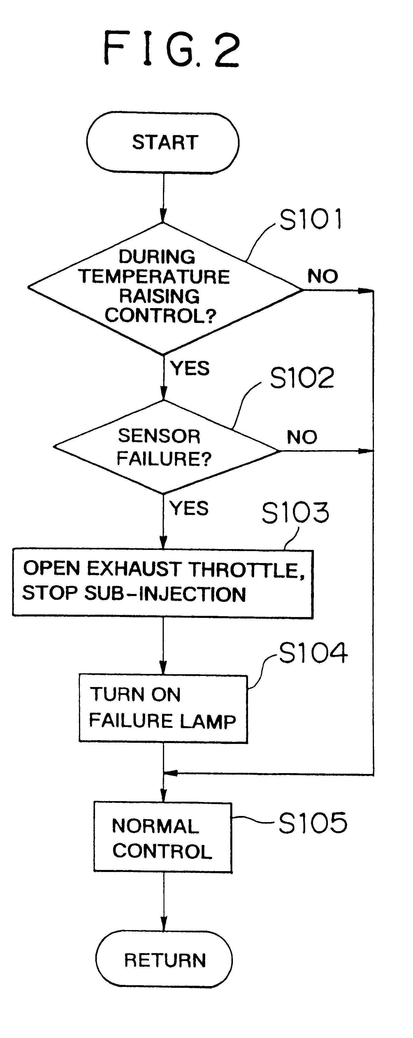
The second embodiment differs from the first embodiment as follows.

In the first embodiment, the operation of the exhaust gas temperature increase means is stopped when a failure occurs in a sensor that is an exhaust gas temperature increase monitor means. In the second embodiment, when a value provided by an exhaust air temperature sensor or a back pressure sensor that indicates a temperature of exhaust gas is different from a predetermined value, it is simply determined that the exhaust temperature raising apparatus has an abnormality, aside from the determination as to which part of the exhaust temperature raising apparatus has an abnormality, and the operation of the exhaust gas temperature increase means is stopped.

Therefore, the content of a program for stopping the operation of the exhaust gas temperature increase stop means and portions related to the content of the program will be specifically described. Portions of the second embodiment substantially the same as those of th...


PUM


Abstract

An exhaust temperature raising apparatus has an exhaust throttle valve that adjusts the engine exhaust amount based on the amount of throttling, and an injector that performs main injection and a sub-injection directly into a cylinder, a combination of an ECU, the injection and the exhaust throttle valve as exhaust gas temperature increase apparatus for, during an engine warm-up, performing and controlling the exhaust throttling by the exhaust valve and performing and controlling an exhaust gas temperature increase through combustion attributed to the main injection performed in an excess-air condition and combustion attributed to the sub-injection, an exhaust gas temperature sensor that monitors a state of temperature increase of the exhaust gas caused by performance of the exhaust gas temperature increase apparatus, and the ECU as monitor abnormality detection apparatus for determining whether the exhaust gas temperature sensor has an abnormality, and the ECU as exhaust gas temperature increase stop apparatus for stopping the operation of the exhaust gas temperature increase apparatus when the ECU determines that the exhaust gas temperature sensor has an abnormality.

Description

INCORPORATION BY REFERENCEThe disclosure of Japanese Patent Application No. 11-304388 filed on Oct. 26, 1999 including the specification, drawings and abstract is incorporated herein by reference in its entirety.1. Field of the InventionThe present invention relates to an exhaust temperature raising apparatus and method for an internal combustion engine.2. Description of the Related ArtDiesel engines produce large amounts of unburned HCs during low-load engine operations, and particularly during a warm-up operation, since the combustion chamber temperature is low during such operations.There is a known technology in which an exhaust control valve is disposed in an engine exhaust passage, and the combustion chamber temperature is raised by closing the exhaust control valve and increasing the amount of fuel injected, so as to curb production of unburned HCs (see, for example, Japanese Patent Application Laid-Open No. SHO 49-80414).When the exhaust control valve is substantially comple...

Claims


Application Information

Patent Timeline
Patent Type & Authority Patents(United States)
IPC IPC(8): F02D41/22F02D9/04F02D9/00F02D41/02F02D41/40F01N3/24F02D41/06F02D41/34F02D43/00F02D45/00
CPCF02D9/04F02D41/024F02D41/405F02D41/221Y02T10/26Y02T10/44Y02T10/12Y02T10/40
Inventor ASANUMA, TAKAMITSUHIROTA, SHINYATOSHIOKA, SHUNSUKEOHASHI, NOBUMOTO
Owner TOYOTA JIDOSHA KK
Why Eureka
Try Eureka