System for high power RF plasma processing

a plasma processing and high-power technology, applied in plasma techniques, transportation and packaging, gated amplifiers, etc., can solve the problems of limiting the maximum bus voltage, reducing the range of application of radio frequency generators, and increasing the cost of pa power supply over the long term, so as to reduce the number and complexity of power components, and enhance the scope of application of such generators. , the effect of small and light weigh

Inactive Publication Date: 2002-05-07
ADVANCED ENERGY IND INC
View PDF11 Cites 66 Cited by
  • Summary
  • Abstract
  • Description
  • Claims
  • Application Information

AI Technical Summary

Benefits of technology

It is an object of this invention to provide a cost effective, reliable, simple design for a plasma power generator.
Accordingly, the present invention provides novel designs which utilize directly rectified mains power in powering relatively lower voltage Power Amplifiers, and may thus eliminate both the bulky and heavy line transformer and the alternative costly switchmode power converter. In one embodiment, it may do this by arranging the circuits so that the rectified mains voltage (the "bus" power) is divided among a number of PA units. The present invention also discloses a method of providing drive to the PA units which is not only simple but provides more output power for each PA unit than prior art drive techniques. The present invention also discloses methods of providing power connections to the PA units with the property of stabilizing the PA against spurious oscillations. The present invention also discloses simple methods of combining, summing, or adding together, output signals from a plurality of amplifiers, and discloses how such a plurality of amplifiers can be arranged to drive a single output tuned circuit so that tuning of the combined array is made simple and easy. Finally, a method is presented to permit higher open circuit voltage and short circuit current from a radio frequency generator operated from a fixed-voltage power source.

Problems solved by technology

In the radio frequency field, generally the former approach (varying the drive signal) is less expensive to implement, because providing a variable voltage dc power supply for the PA bus is more costly than providing for a variable drive signal.
Most transistors suitable for radio frequency cannot withstand very high voltages, however, and this limits the maximum bus voltage.
All of these effects add to produce peak voltage levels which can be too large for typical radio frequency transistors to withstand.
In addition to these problems related to the transistors, in the commonly used "push-pull" circuits a transformer is utilized which typically contains ferrite cores, and the losses in these cores can become unmanageable at high dc supply potentials.
These transformers are heavy and bulky in high power circuits which we here define as those over about 100 watts.
Such power converters are usually costly due to their complexity and this constitutes a disadvantage.
This second power control approach does solve another problem found in the fixed voltage method first described, which is that with a fixed power supply the power dissipation in the transistor devices can become excessive into some mismatched loads.
So heretofore the designer of such high power radio frequency generation equipment has in many cases been faced with the following dilemma: accept the large and heavy result of incorporation of a line transformer or incorporate a switchmode power converter with its high cost.
This dilemma can exist regardless of the need to control the output of the equipment.
This has been done because, until recently, semiconducting transistors capable of producing powers much above about 300 watts were not practically available, and those that exist may require special circuits to make use of them.

Method used


Image

  • System for high power RF plasma processing
  • System for high power RF plasma processing
  • System for high power RF plasma processing

Examples


Embodiment Construction

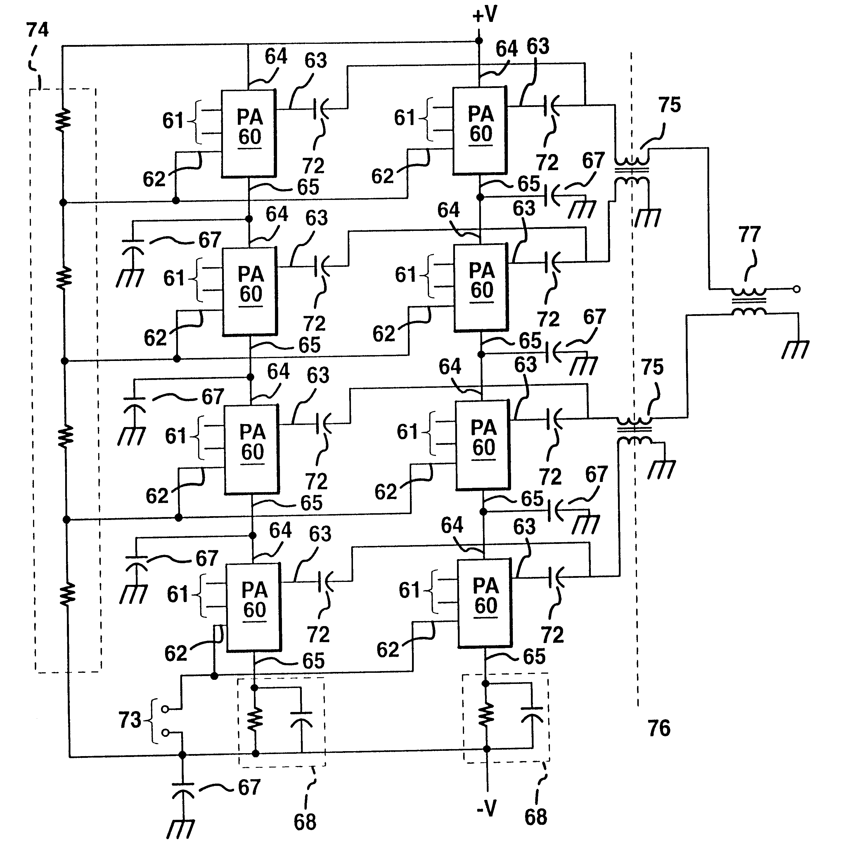
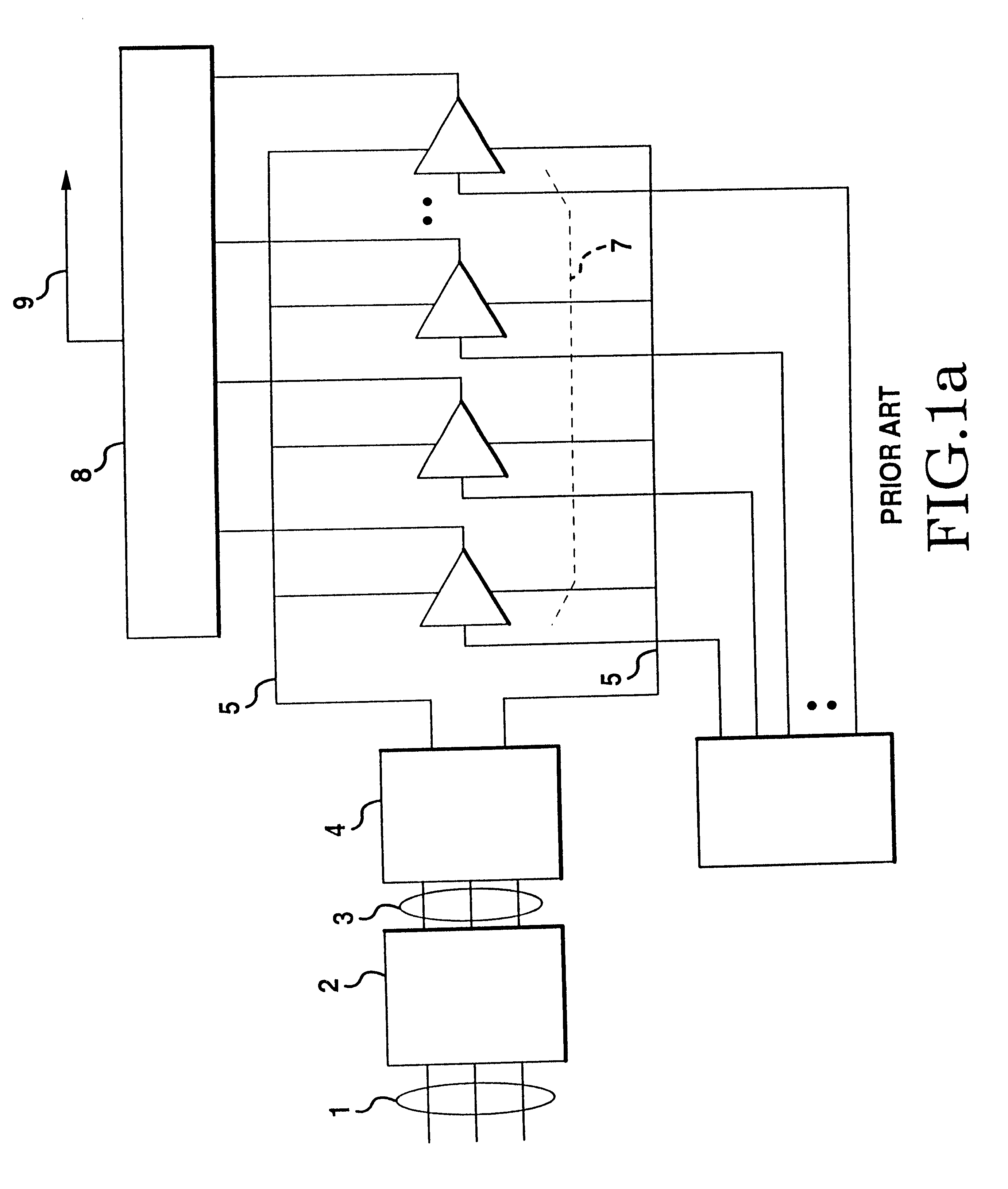
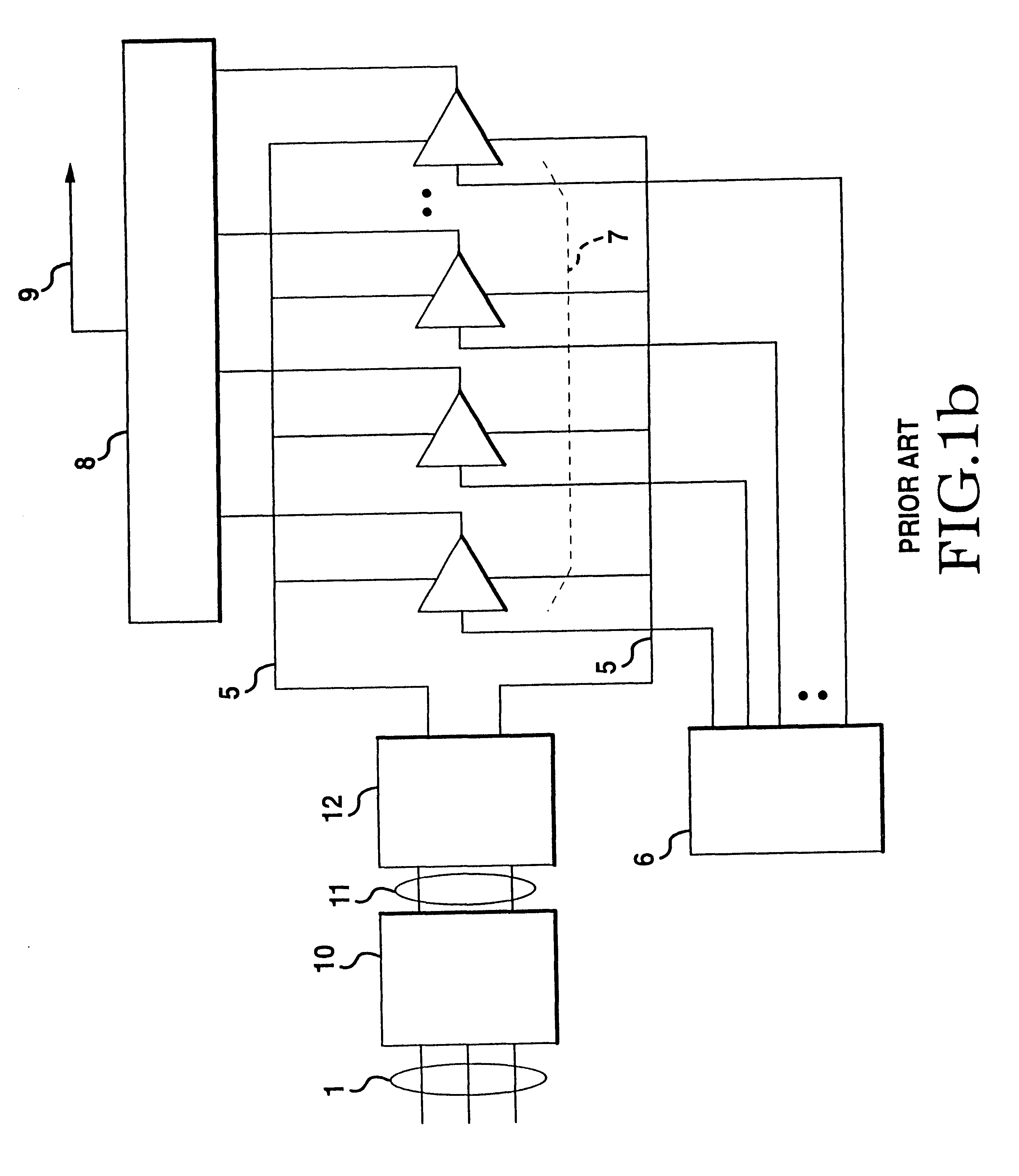
As mentioned above, the present invention presents improved circuits and circuit configurations for production of radio frequency high power signals. This may be most easily seen by comparison to the prior art. In the prior art, the incoming mains power supply is reduced in voltage to be compatible with the lower voltage capability of the power amplifying devices. As has been said, this can be accomplished in several ways, two of which are shown in FIG. 1.

FIG. 1a shows a common basic configuration of the prior art. Power from the incoming supply 1 (such as the mains supply) is transformed by transformer 2 to a lower alternating voltage 3. This lower voltage 3 is converted to dc bus voltage 5 by AC-DC converter 4. This bus voltage 5 is supplied to a plurality of power amplifiers (PAs) 7, by parallel connection. That is, each of the plurality of PA units 7 is supplied the same bus voltage 5. Naturally, there may be in some cases only a single PA unit, but if higher powers are required...


PUM


Abstract

A high power radio frequency power method of amplifications described in which a variety of amplifiers (60 & 86) may be used to reduce the stress any one amplifier experiences. The power leads (64 & 65) may be arranged in a series to power each amplifier at potentials which are lower than the total potential. Outputs (63) may then be connected in a parallel fashion to combine the power output by the system. A variety of unique stabilization, drive, division, combination, and supply configurations are presented as well as the possibility of utilization and adaptation of the designs for a plasma processing system. An aspect of tiered combining is included such as may be especially appropriate for larger numbers of devices which may include switchmode amplifiers and the like.

Description

I. TECHNICAL FIELDThis invention generally relates to radio frequency generators which accept a power such as a dc potential and convert that power into a radio frequency, higher power output. More particularly it relates to such generators which produce power which are considered especially high when compared to those typically created from a particular type of component or particular design. The invention also may involve enhanced systems and processes (including plasma processing systems, and the like) which may include a variety of ancillary features such as these higher power generators, system specific elements, or unique processes.DefinitionsApproximately EqualIn this context, voltages, currents, impedances, or other quantities are approximately equal if the differences between them are not significant in the context of the particular application or the particular design or componentry involved and, as such, do not cause an effect which is so different in that context as to m...

Claims


Application Information

Patent Timeline
Patent Type & Authority Patents(United States)
IPC IPC(8): B41J15/00B41J13/10B65H29/62B65H35/00B65H29/26B65H29/00B65H29/12H03F3/20H03F3/217H03F3/21H03F3/72H05H1/46H01L21/302H01L21/3065H03F1/02H03F3/68
CPCH03F3/211H03F3/72H03F3/2176H03F3/21
Inventor PORTER, JR., ROBERT M.LEDENEV, ANATOLI V.GUROV, GENNADY G.
Owner ADVANCED ENERGY IND INC
Why Eureka
Try Eureka