
Apparatus and method therefor of maximizing the production run speed of a sheet fabrication machine

a technology of sheet fabrication machine and production run speed, which is applied in the direction of total factory control, programme control, electric programme control, etc., can solve the problems of inability to meet the requirements of just in time production, and inability to meet the requirements of production accuracy at the fastest possible speed at which a sheet fabrication machine can operate, so as to achieve the maximum productivity and the effect of required accuracy

Inactive Publication Date: 2002-05-28
FINN POWER INT
View PDF3 Cites 26 Cited by
  • Summary
  • Abstract
  • Description
  • Claims
  • Application Information

AI Technical Summary

Benefits of technology

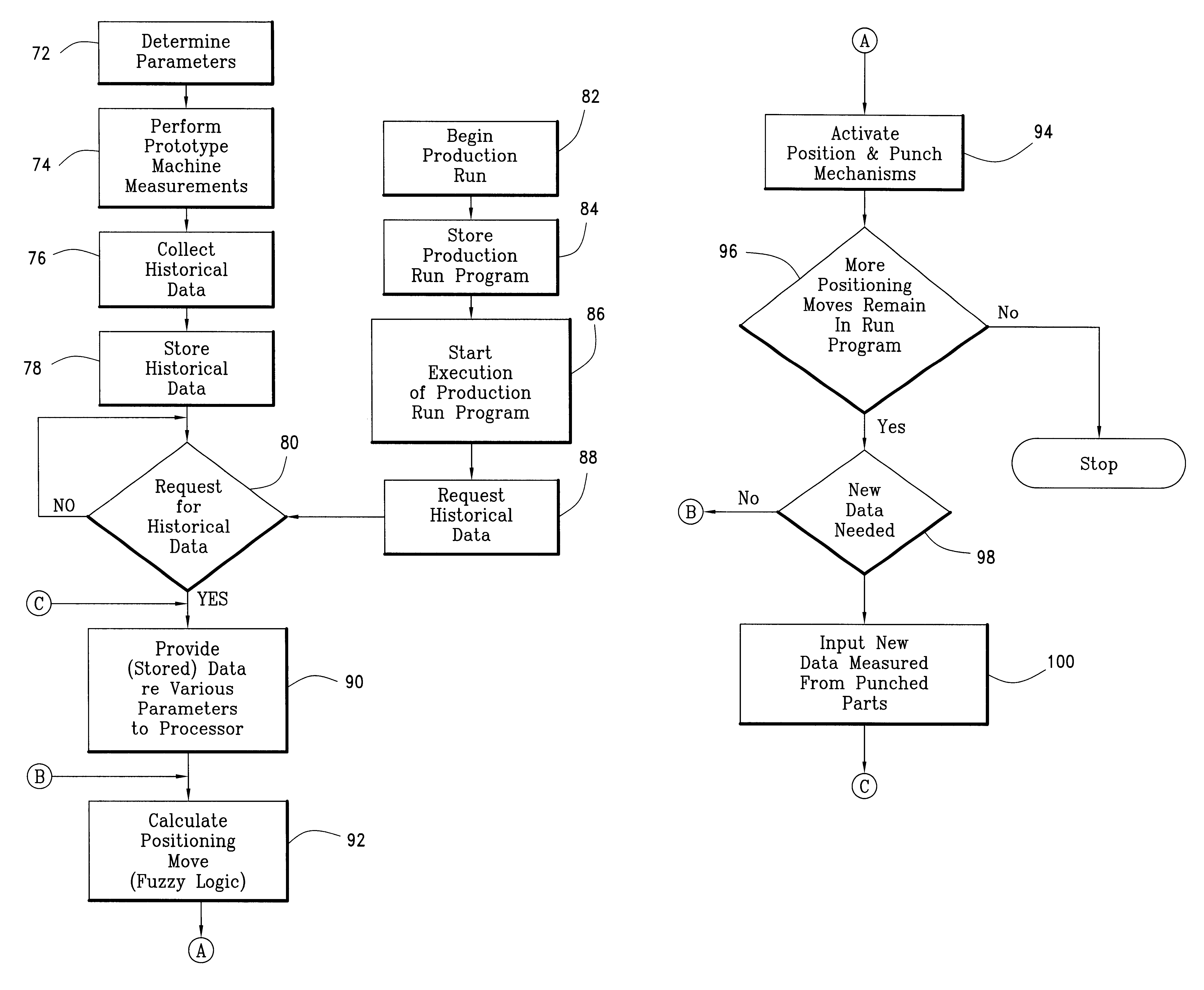
To enable the processor of the sheet fabrication system to calculate each positioning move optimally, fuzzy logic, either in the form of software or as an add-on module that can be obtained commercially, is provided to the processor of the system. Data relating to the required hole to hole tolerance for a part is input to the processor for each type of sheet blank so that the processor of the system can calculate the optimal positioning move to maximally produce parts from each sheet blank type. Depending on the tolerance required, the processor can instruct the machine to operate at a given pace--setting positioning parameters to effect a "slower" production speed, i.e. less productivity in quantity but better quality, when the tolerance for producing a particular positioning requirement is high, and faster production speed, i.e. higher productivity, when the tolerance requirement is "loose". Furthermore, by providing historical data to the fuzzy logic, the processor of the system is able to learn to make positioning corrections to compensate for normal wear of the machine, the particulars in some areas of the worktable of the machine and other happenstance that relates to the machine.

Problems solved by technology

But the demand for just in time production substantially reduces, if not completely eliminates, the time available for testing the suitability of a particular nesting of parts for a given dimensioned worksheet for fast and accurate production of the different parts from the worksheet.
Yet this requirement to produce accurate parts at the fastest possible speed at which a sheet fabrication machine can operate is frustrated up to now because of the deflections and vibrations that are inherent in the structure of sheet fabrication machines.
These inherent deflections and vibrations are caused by the moving components of each sheet fabrication machine such as for example the high torque axes drive systems of a turret punch press.
When supporting loads, the weight of the loads will further cause deflections or vibrations in the mechanical structure of the sheet fabrication machine and its axes guide system.
The deflection causing forces increase with the size of the worktable and the size of the worksheet being introduced to the machine.
However, the design of a non-deflecting mechanical structure for a sheet fabrication machine capable of handling high loads with high positioning speed would be very expensive, if not down right impossible to achieve with present day technology.
However, this methodology requires constant interfacing by the operator or programmer of the machine, and is highly dependent on the individual skills of the operator / programmer.
This however results in the sheet fabrication machine not being used to its fullest potential, thus resulting in longer production time and lesser throughput.

Method used


Image

  • Apparatus and method therefor of maximizing the production run speed of a sheet fabrication machine
  • Apparatus and method therefor of maximizing the production run speed of a sheet fabrication machine
  • Apparatus and method therefor of maximizing the production run speed of a sheet fabrication machine

Examples


Embodiment Construction

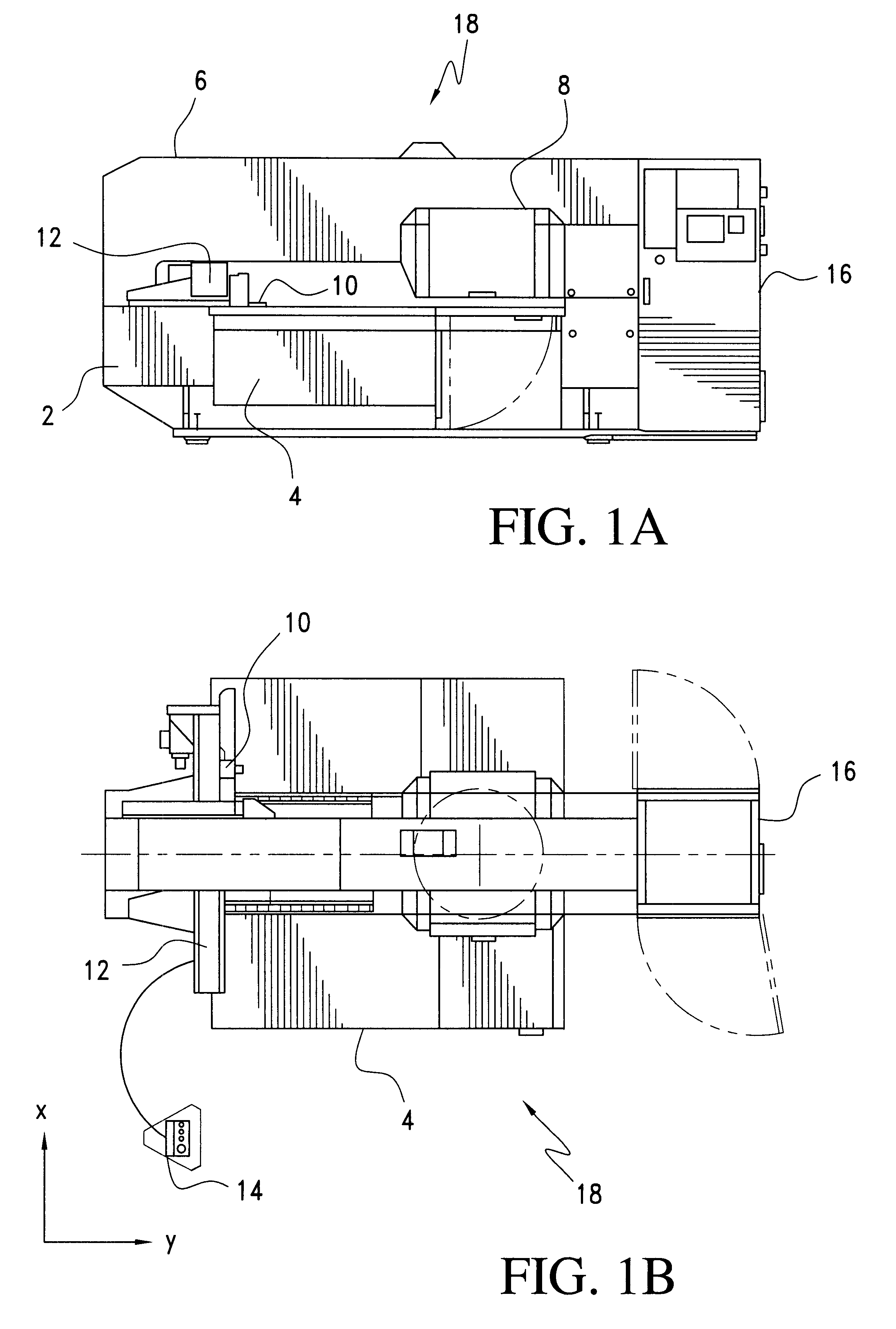
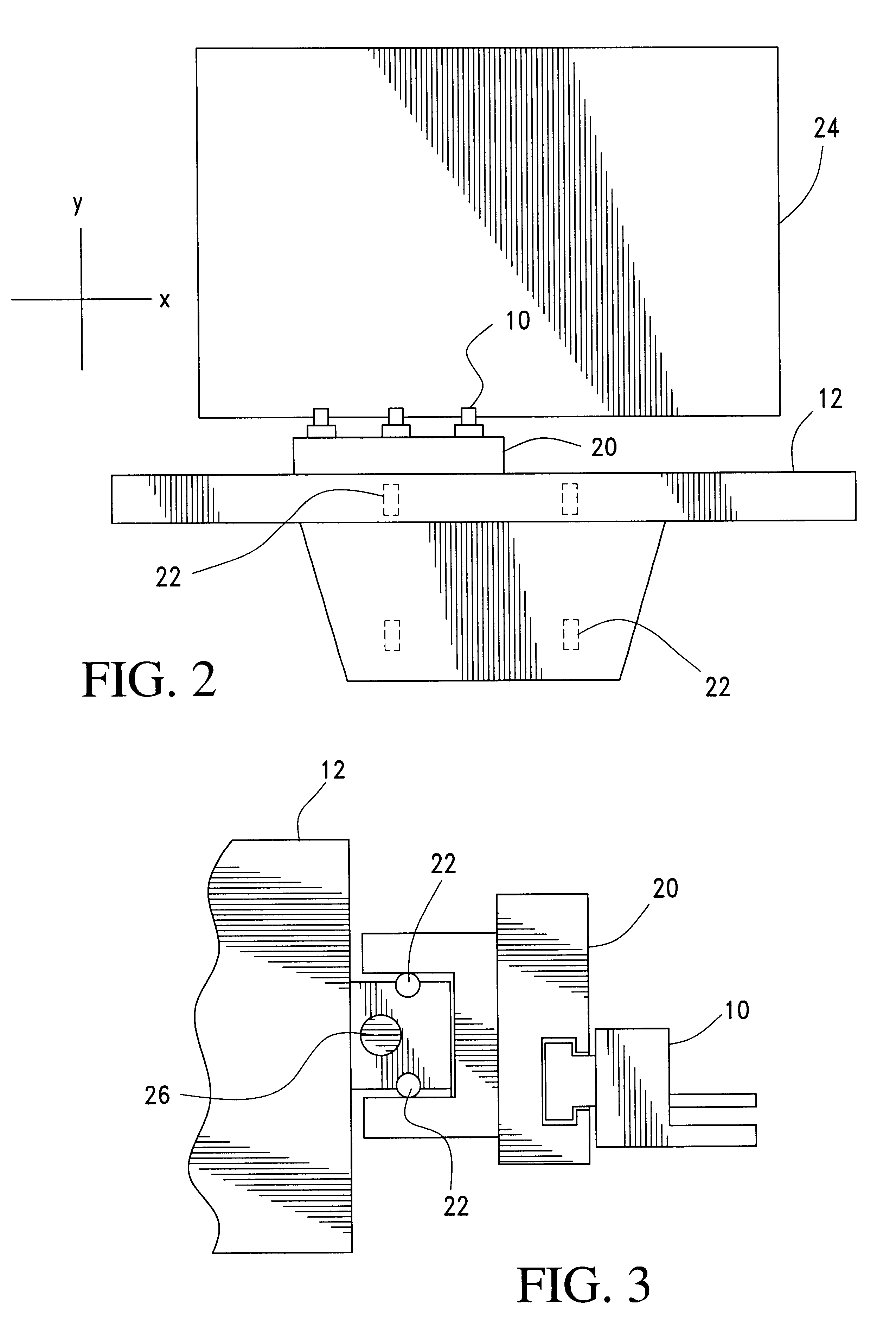
With reference to FIGS. 1A and 1B, a sheet fabrication machine such as for example a turret punch press in a sheet fabrication center is shown to have a base 2 to which is coupled a worktable 4. The area of the worktable is shown in the plan view of FIG. 1B. Mounted to base 2 is a frame 6 to which a turret may be mounted. Tools are mounted along the periphery of the turret for punching holes in a sheet blank or worksheet being held by clamps 10 mounted to a slide and a carriage 12. Carriage 12 is moveable along the x axis while holder clamps 10 (or any other means to move the workpiece), by means of the slide being movably coupled to carriage 12, are moveable along the y axis. See

FIG. 1B. Accordingly, a worksheet held by clamps 10 can be moved anywhere along the work area of worktable 4.

Although not shown, a punch, and its related drive mechanism, is positioned to drive a tool mounted to a turret (or any other tool carrier since where the tool is mounted is not important) that has b...


PUM


Abstract

To maximize the production run speed of a sheet fabrication machine such as a turret punch press, and yet at the same time maintaining the requisite accuracy for each part produced from the production run, historical data pertaining to the various parameters for effecting the positioning moves of a worksheet are measured and collected using a reference machine or a prototype machine. For each positioning move to be effected, the CNC controller of the system retrieves the historical data from a database and, using that historical data, calculates the various parameters that affect the positioning move. By using fuzzy logic, the controller becomes, in a sense, self teaching, especially if updated historical data are provided to its database store to enhance the accuracy for later positioning moves. In addition to measuring and collecting historical data from reference or prototype machines, static process control (SPC) tests may be performed for different types of worksheets under different loads. The data collected from the SPC tests are stored and can be used as the historical data. Using historical data to calculate the next positioning move, i.e., by using the past to forecast or predict the future, the maximum allowable speed is obtained for each positioning move. At the same time moves that will produce parts that have dimensions that are within the predetermined required accuracy threshold are ensured.

Description

The present invention relates to numerically controlled sheet fabrication centers and / or machines, and particularly relates to an apparatus and method for maximizing the speed of fabricating from a sheet blank, with the dimensional accuracy of the produced parts being maintained above a predetermined threshold.In a production run of a sheet fabrication machine, such as for example a turret punch press in a flexible manufacturing system (FMS) or a sheet fabrication center, large sheet blanks or worksheets are used. This is due mainly to: (1) the capability provided in currently available software that allows an operator / programmer to program fabrication of multiple parts from a single large worksheet, and (2) the increasing size of sheet fabrication machines such as hydraulic turret punch presses that allows large worksheets to be processed. The programming of multiple different parts to be cut from a single worksheet is moreover made possible with the onset of nesting programs which...

Claims


Application Information

Patent Timeline
IPC IPC(8): G05B19/418
CPCG05B19/41875G05B2219/32018G05B2219/34065Y10S706/904G05B2219/36101G05B2219/42134G05B2219/45131G05B2219/34327Y02P90/02Y02P90/80
Inventor LINDSTROM, MIKKOTAIJONLATHI, JORMA
Owner FINN POWER INT
Learn More