Solid cable, manufacturing method thereof, and transmission line therewith

a technology of solid cable and manufacturing method, applied in the direction of power cables, cables, insulated conductors, etc., can solve the problems of reducing the electric performance conspicuously, the cable line is too long to feed or absorb insulating oil at both ends, and cannot be realized

Inactive Publication Date: 2002-06-04
SUMITOMO ELECTRIC IND LTD
View PDF19 Cites 15 Cited by
  • Summary
  • Abstract
  • Description
  • Claims
  • Application Information

AI Technical Summary

Benefits of technology

Generally, a metal sheath (usually a lead sheath) is provided on the outer circumference of an insulation layer of a solid cable. It is also preferable to form a reinforcing tape layer on the outer circumference of this metal sheath. This reinforcing tape layer has a function to have its share against hoop stress (stress generated inside the metal sheath by oil pressure to break the metal sheath) exerted on the metal sheath to thereby reinforce the metal sheath. Therefore, it is preferable to select the material of the reinforcing type layer from the materials which can obtain a high tensile strength, for example, from polyamide, polyimide resin tape (trade name; Kevlar), etc. as well as a metal tape such as stainless steel.

Problems solved by technology

They cannot be realized unless a new technique is developed.
That is, particularly in the case of a long-distance submarine solid cable, the cable line is too long to feed or absorb insulating oil at its both ends.
However, the following problems arise as conspicuous hurdles for making both service voltage and service temperature of the conventional solid cables high to ensure the large capacity thereof.
Since the high-viscosity oil cannot move sufficiently rapidly from the outside of the insulating wall to the inside thereof, sometimes starvation of the insulating oil occurs near the conductor which may produce voids so that such voids are thereby likely to reduce the electric performance conspicuously.
That is, as the maximum service temperature of the conductor is attempted to make higher, (1) the treatment of the insulating oil becomes more difficult because the amount of the expansion and contraction of the insulating oil is increased, and (2) it becomes more necessary to take measures against the easiness of migration because of lowering of the viscosity of the insulating oil.
In addition, the temperature at the time of load OFF drops down more sharply to thereby cause severe oil-starvation so that large voids are apt to be generated.
Therefore, there is a problem that high electric stress cannot be applied to the cable insulation thoughtlessly.
However, in comparison with kraft paper consisting of porous natural wood pulp fiber, polyolefin resin film has no pores through which liquid can flow so that high-viscosity insulating oil are not allowed to pass.
Therefore, when a cable core is impregnated with insulating oil in a factory with high-viscosity insulating oil, there arises a very serious situation that the impregnation of insulating oil becomes insufficient or impossible, or even if possible very hard to fully implement for an industrially reasonable process time, as the insulation layer is thicker.
As a result, it could be hardly done to improve the industrial productivity or to increase the ratio of the polyolefin resin film in the composite insulating tape in order to achieve the expected purpose.
On the other hand, in a solid cable filled with insulating oil the viscosity of which is extremely high, the fluidity of the insulating oil is contrarily not enough so that the insulating oil shows discontinuity.
In addition, because of the above-mentioned discontinuity of insulating oil, the oil pressure in the insulation itself could not be increased in proportion to the depth of water.
However, this operating system becomes a large obstacle in view of free operation.
On the other hand, sudden temperature drop when load is switched OFF in the state of full load, and oil starvation in the insulation layer near the conductor caused by the oil contraction due to the temperature drop are main concerns.
In an insulation layer including resin film which does not allow the insulating oil to pass, the insulating oil cannot flow without bypassing the resin film tape.
(7) The viscosity is required to be not so low that when a metal sheath of the cable is removed for the jointing work of another cables, the insulating oil inside the cable ins pushed up by the difference of pressure between the outside water pressure in accordance with the water depth and the insulating oil pressure inside the cable so that the insulating oil flows out endlessly to make it difficult to carry out the jointing work.

Method used


Image

  • Solid cable, manufacturing method thereof, and transmission line therewith
  • Solid cable, manufacturing method thereof, and transmission line therewith
  • Solid cable, manufacturing method thereof, and transmission line therewith

Examples


Embodiment Construction

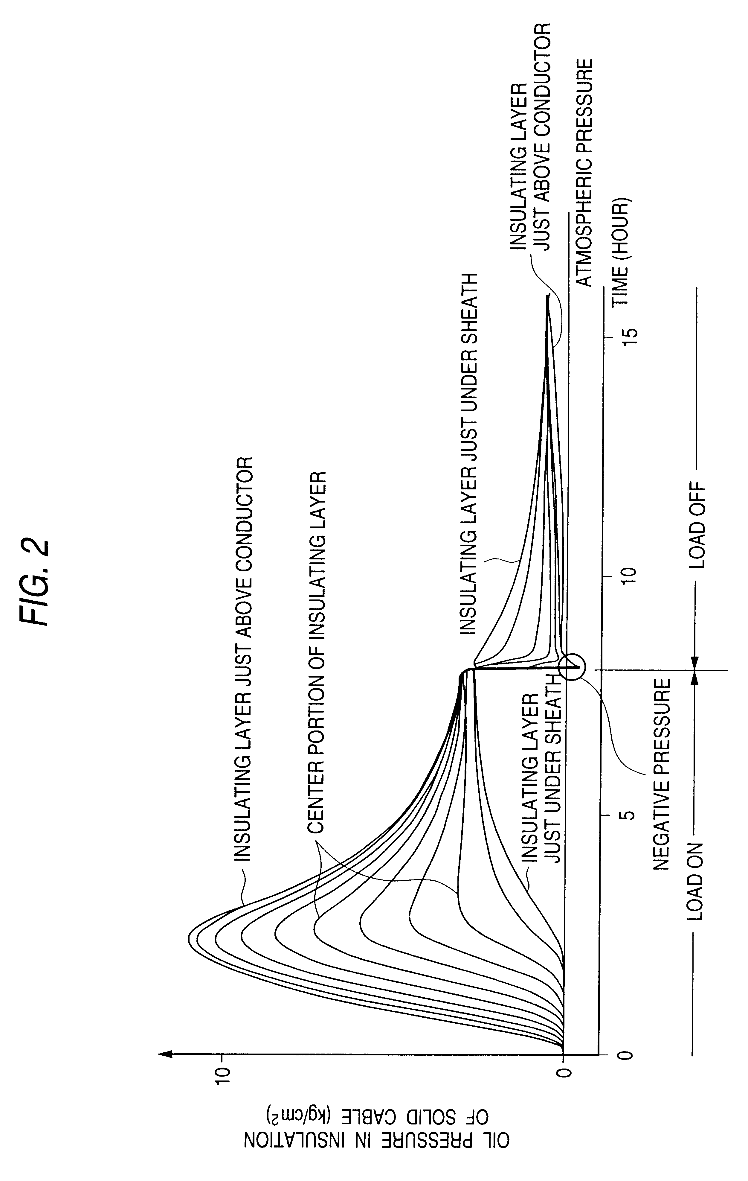
In order to find out insulating oil satisfying the above conditions, the following experiments were performed.

A solid cable with kraft paper insulation in which the insulation thickness was 20 to 25 mm, and which was in the class of 400 to 500 kV, was put in a vessel, and soaked in water. The water pressure was changed to simulate the depth of sea water. The sea-water pressure is expressed by "(water depth (m) divided by 10) (kg / cm.sup.2)".

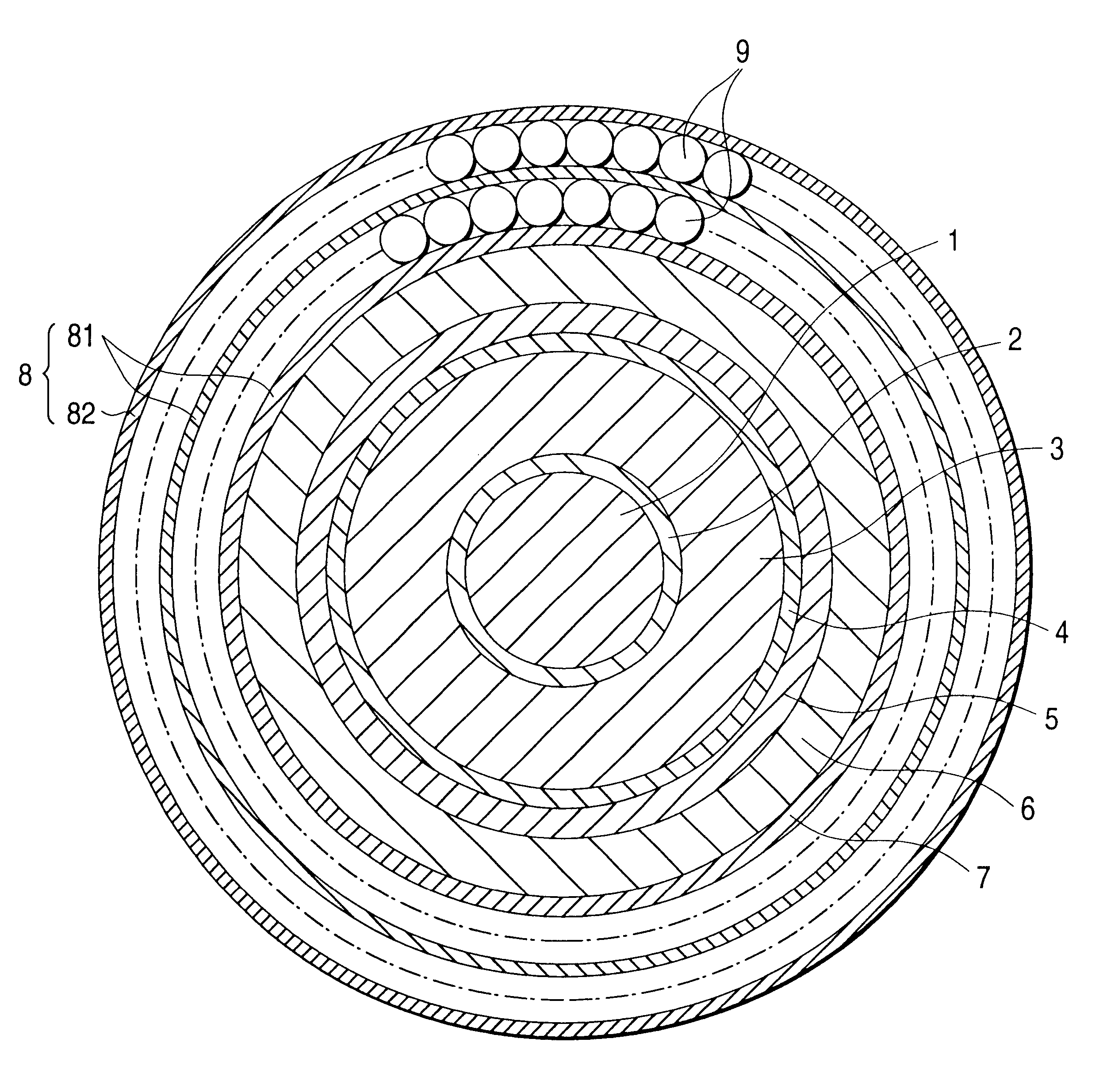
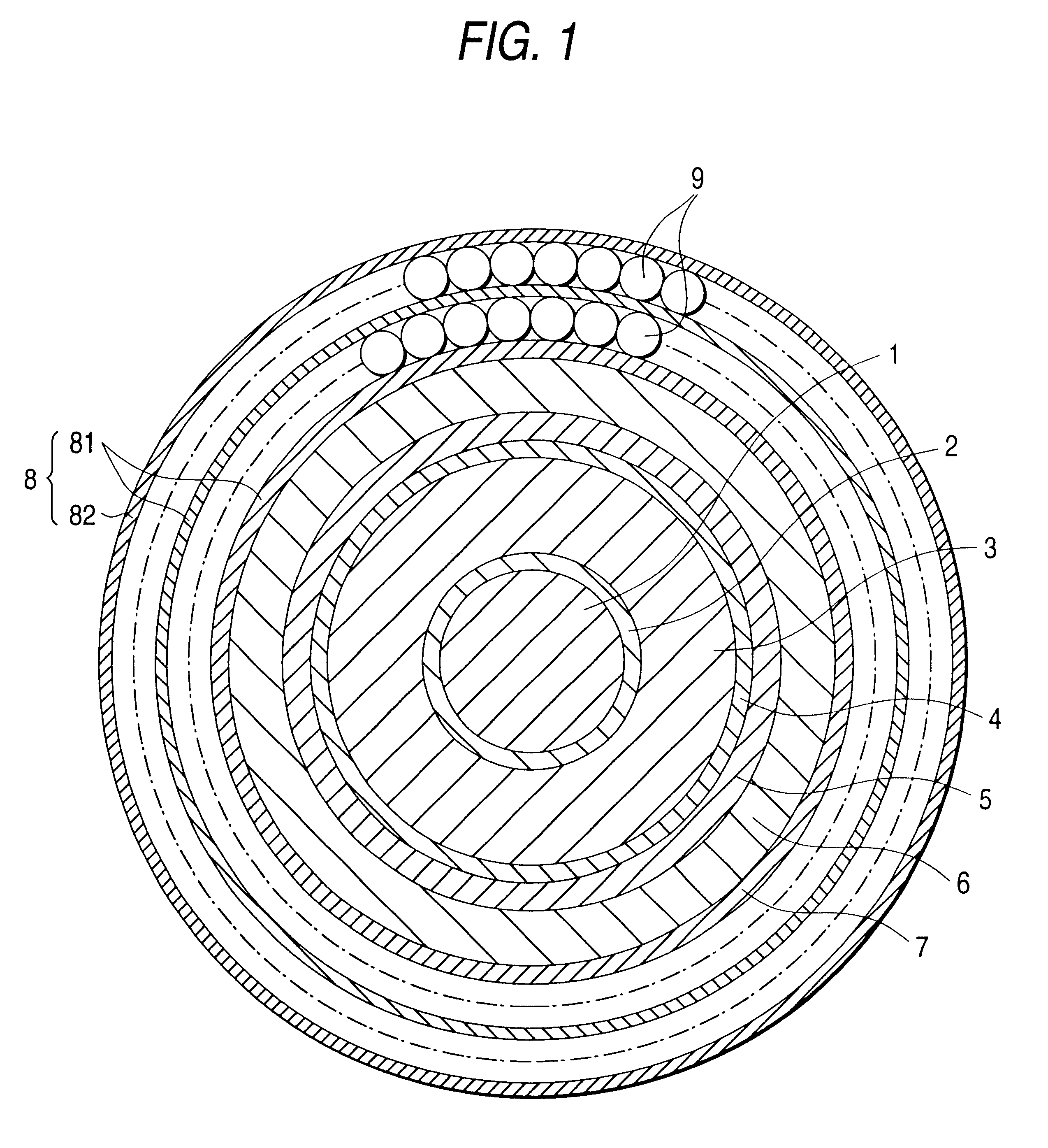
The structure of the used cable is shown in FIG. 1. FIG. 1 is a cross-sectional view illustrating the structure of an example of a DC submarine solid cable. The cable has, in the order from the center, a conductor 1, an inner semiconductive layer 2, an oil-impregnated insulation layer 3, an outer semiconductive layer 4, a metal sheath 5, an anti-corrosive plastic layer 6, a metal tape 7, a protective yarn layer 8 and wire armoring layers 9.

The oil-impregnated insulation layer 3 is configured in the way that a wound kraft paper tape is impregnated ...


PUM

PropertyMeasurementUnit
temperatureaaaaaaaaaa

Abstract

A cable and cable system is provided having a conductor and an insulation layer on an outer circumference of a conductor. The insulation layer is impregnated with a medium-viscosity insulating oil that has a viscosity of 10 centistokes (cst) to less than 500 cst at 60° C. The insulation layer includes an insulating tape that may be one or a combination of composite tape having a polyolefin resin film laminated with a kraft paper on both its sides and an insulating tape including a polyolefin resin film. The cable includes a metal sheath provided on an outer circumference of the insulation layer, and a reinforcing layer formed on an outer circumference of the metal sheath. The reinforcing layer reinforces the metal sheath by absorbing hoop stress exerted on the metal sheath. The cable system includes a submarine-portion cable and a land-portion cable, an oil stop joint box, and an oil feeding tank. The oil stop joint box connects the submarine-portion cable to the land-portion cable, and the oil feeding tank is connected to the land-portion cable which feeds the medium-viscosity insulating oil to the land-portion cable.

Description

1. Field of the InventionThe present invention relates to a power cable which is optimum for long-distance and bulk power transmission, and particularly to a structure and a method of manufacturing for a power cable for DC submarine transmission and a submarine transmission line using such power cables.2. Description of the Related ArtConventionally, a solid cable (Mass-Impregnated Cable or Non-Draining Cable) using kraft paper as insulating tape material and impregnated with high-viscosity insulating oil (for example, 25 to 100 cst at 120.degree. C., and 500 to 2,000 cst at the maximum service temperature of the cable (50 to 60.degree. C.)) has been used as a long-distance and bulk power DC cable.To attain a solid cable of a larger capacity, it will do to make the solid cable withstand a higher voltage and allow a larger current. A large current solid cable can be realized if a conductor having a sectional area as large as possible is used or the maximum service temperature of the ...

Claims


Application Information

Patent Timeline
Patent Type & Authority Patents(United States)
IPC IPC(8): H01B3/44H01B3/28H01B7/14H01B3/22H01B9/00H01B7/17H01B3/18H01B9/06H01B7/29H01B13/00H02G15/24
CPCH01B3/22H01B3/28H01B3/441H01B9/0688H01B7/292H01B9/0611H01B7/14
Inventor KONDO, MAMORUHATA, RYOSUKETAKIGAWA, HIROSHIYORITA, JUNHORIKAWA, TAKAHIROASHIBE, YUICHISEKI, MORIHIRO
Owner SUMITOMO ELECTRIC IND LTD
Why Eureka
Try Eureka