
Electrodynamic field generator

Inactive Publication Date: 2002-06-11
LV DYNAMICS
View PDF15 Cites 103 Cited by
  • Summary
  • Abstract
  • Description
  • Claims
  • Application Information

AI Technical Summary

Problems solved by technology

However, key differences and limitations with regard to achieving this objective are in evidence.
The proposed arrangement is furthermore limited to operation within a gaseous dielectric medium, upon which it is reliant for the production of the claimed motive force, and is to be operated at a potential gradient less than that which would produce a visible corona.
This same device evidences a great deal of theoretical complexity and construction material specificity, which might seem to indicate a narrow range of feasibility.
This said other device, however, relies upon the questionable concept that the very large angular momentum of the rotating flywheel is somehow able to compensate the potential energy caused by gravitation and that the overall weight of the apparatus may thereby be annulled.
In this respect it may be stated that none of these related art devices attain the distinction of being able to operate extensively in the vacuum of space without the onboard storage of relatively massive reaction material for the production of thrust.
Finally, it is observed that none of the aforementioned related art devices can develop this type of useful thrust-producing electrodynamic field in a manner which allows more than one objective function to be fulfilled thereby, such as the production of useable thermal kinetic energy and / or the development of potential signal communications capability.
The first part of the problem in this respect is that it is not possible to produce this kind of voltage directly within a traditional generating coil arrangement, so the voltage applied to the charged housing sections must be achieved by special electrostatic means.

Method used


Image

  • Electrodynamic field generator
  • Electrodynamic field generator
  • Electrodynamic field generator

Examples


Embodiment Construction

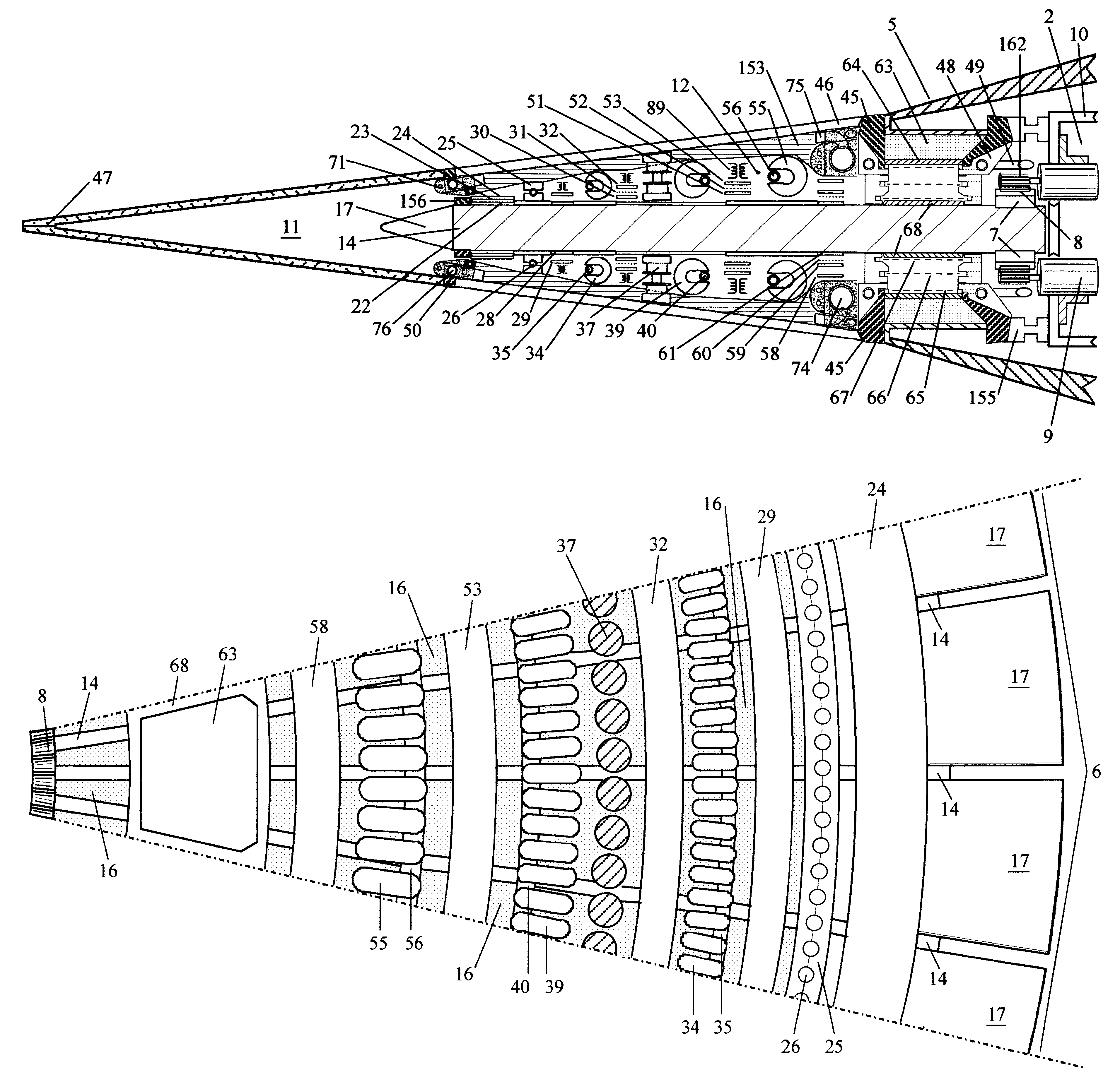
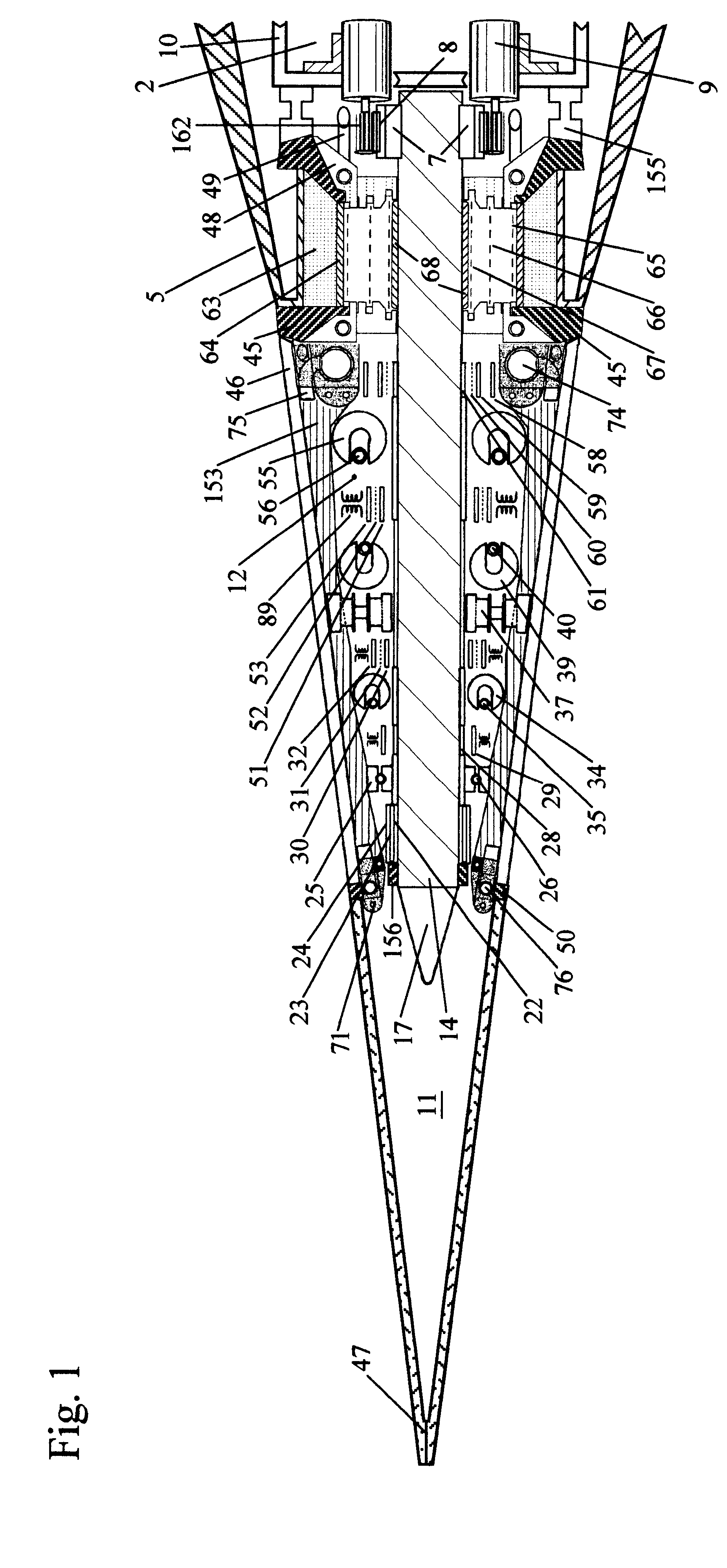
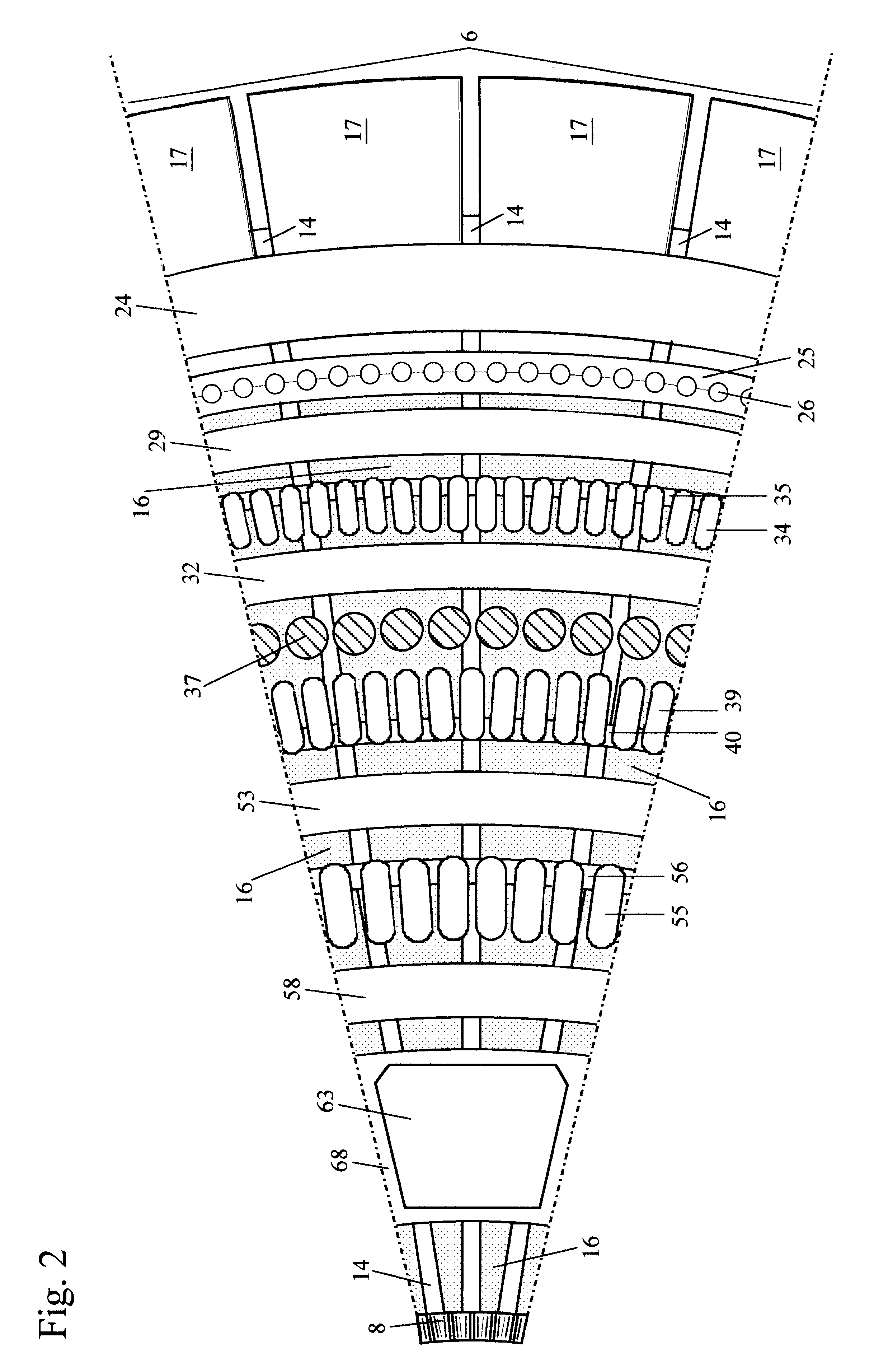
Accordingly, referring to FIGS. 1 through 4, the present invention constitutes a novel form of brushless permanent magnet electrical generator for producing a useful ultra-high-energy external electrodynamic field, or continuous quasi-coherent DC corona or arc discharge of essentially uniform current density, and as such the Generator fundamentally comprises and incorporates:

[A] a flat conductive rotor (6) principally formed of a large number of evenly-spaced individual metallic conductors or segments (14) and an equal number of conductive electron-emitting elements or field emitters (17), radially arranged in an annular flywheel configuration rather like the rotatable deck of a carousel, which are all connected in parallel electrically by the attachment of a thin metallic electrode ring (68) about the positive inner circumference of each of the two major flat faces of the annular flywheel thus formed and by the attachment of another such ring (22) about the negative outer circumfer...


PUM


Abstract

This device is a brushless high-voltage electrical generator, requiring suitable means of input rotary torque, for purposes of producing a very-high-energy external electrodynamic field or continuous quasi-coherent DC corona or arc discharge of uniform current density which completely encloses the machine's conductive housing. This housing is divided into distinct electrical sections and contains a flat conductive rotor which electrically links separate negative and positive housing sections and upon which a plurality of toroidal generating coils are rotatably mounted. Circular arrays of stationary permanent magnets are affixed within the housing which induce a constant DC voltage within said coils upon their rotation. The primary voltage so-generated is electrostatically impressed across the rotor such that great quantities of electronic charge may be transported between the opposite polarity sections of the housing, in such a manner that a much higher secondary voltage is caused to appear across interposed neutral sections thereof, and the resulting external breakdown current once initiated is independent of the generating coils' ampacity. Ancillary mechanical, electrical, an / or electronic features may be attached upon or within the housing to aid in harnessing and controlling the useful effects associated with the external dynamic electric field produced by the device.

Description

The present invention is related in general to rotary direct current (DC) electrical generators which incorporate permanent magnet fields, and in particular to similar electromechanical generating devices whose principal purpose is to produce a useful continuous high-voltage DC corona discharge. This invention also pertains to the field of aerospace vehicles which are capable of propulsion through the utilization of an ultra-high-voltage corona or arc discharge of a special type and form.DESCRIPTION OF RELATED ARTIn order to provide background information so that the present invention may be completely understood and appreciated in its proper context, reference is made hereinbelow to a number of related art patents. These cited references contain certain similarities to the present invention, primarily related to the objective of producing electrically-developed thrust. However, key differences and limitations with regard to achieving this objective are in evidence.The related art d...

Claims


Application Information

Patent Timeline
IPC IPC(8): B64C39/00H02N11/00H05H1/24H02K21/28H05H1/54
CPCB64C39/001H05H1/24H02N11/006H05H1/47H01J37/32339
Inventor TOMION, MARK R.
Owner LV DYNAMICS
Learn More