Unfortunately, when this is done, the
transverse mode structure of the resulting broad area
laser becomes multimode, and the
laser output is no longer sufficiently coherent to be coupled into a single-mode fiber.
This is a very inefficient shape for a double clad device.
Polymer-clad fibers are less stable thermally and mechanically than silica fibers, and they can be easily damaged by the pump
radiation.
Non-concentric fibers are difficult to align and splice.
The fact that the fibers are not round makes it difficult to combine these fibers with more standard fiber components and to
exploit the existing infrastructure of tools such as fiber cleavers, splicers, and ferrules that are optimized for use with round optical fibers.
However, in an
amplifier, signal power that is coupled into the multimode
waveguide could give rise to signal distortions when this signal is accidentally amplified and coupled back into the output signal.
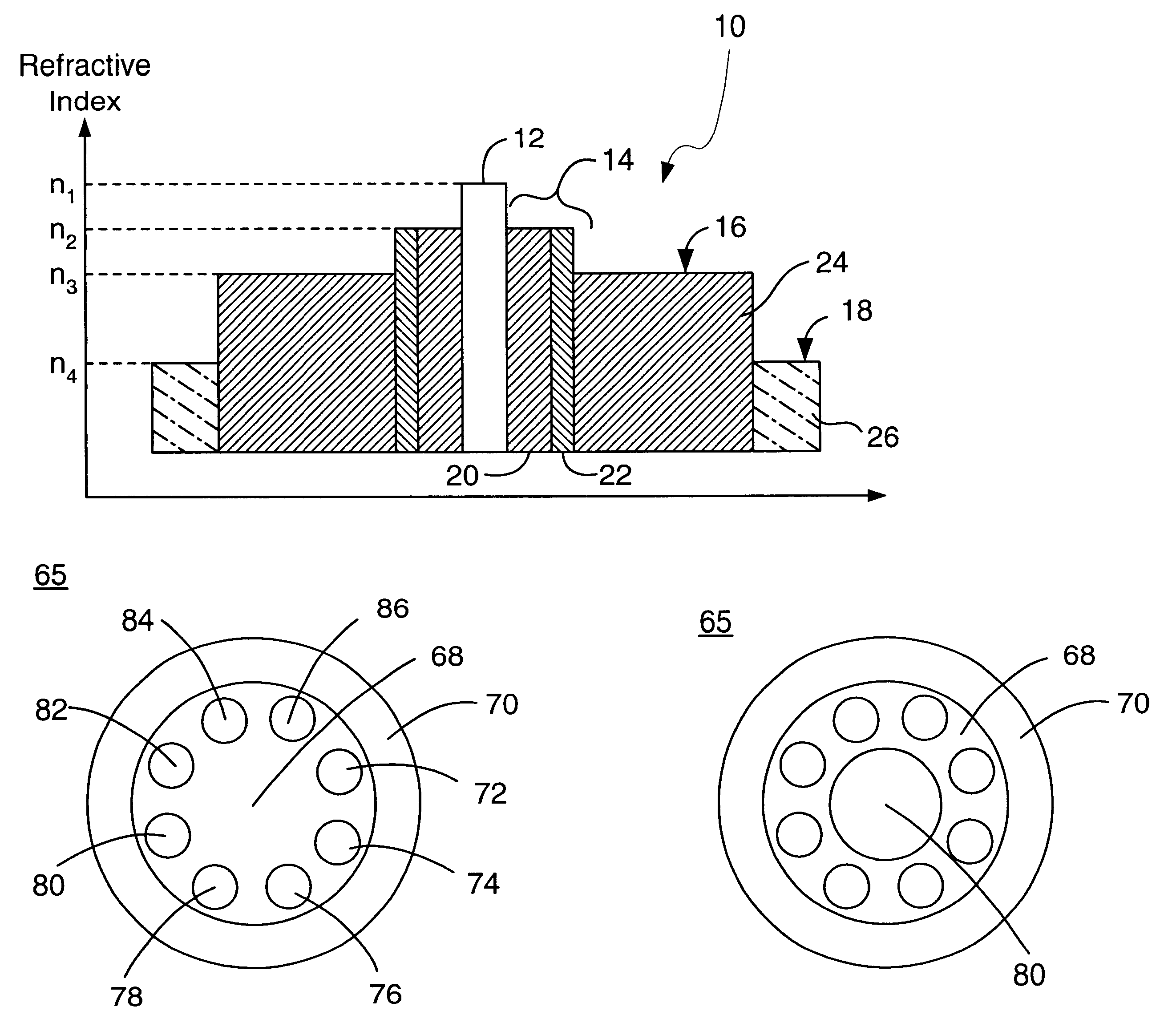
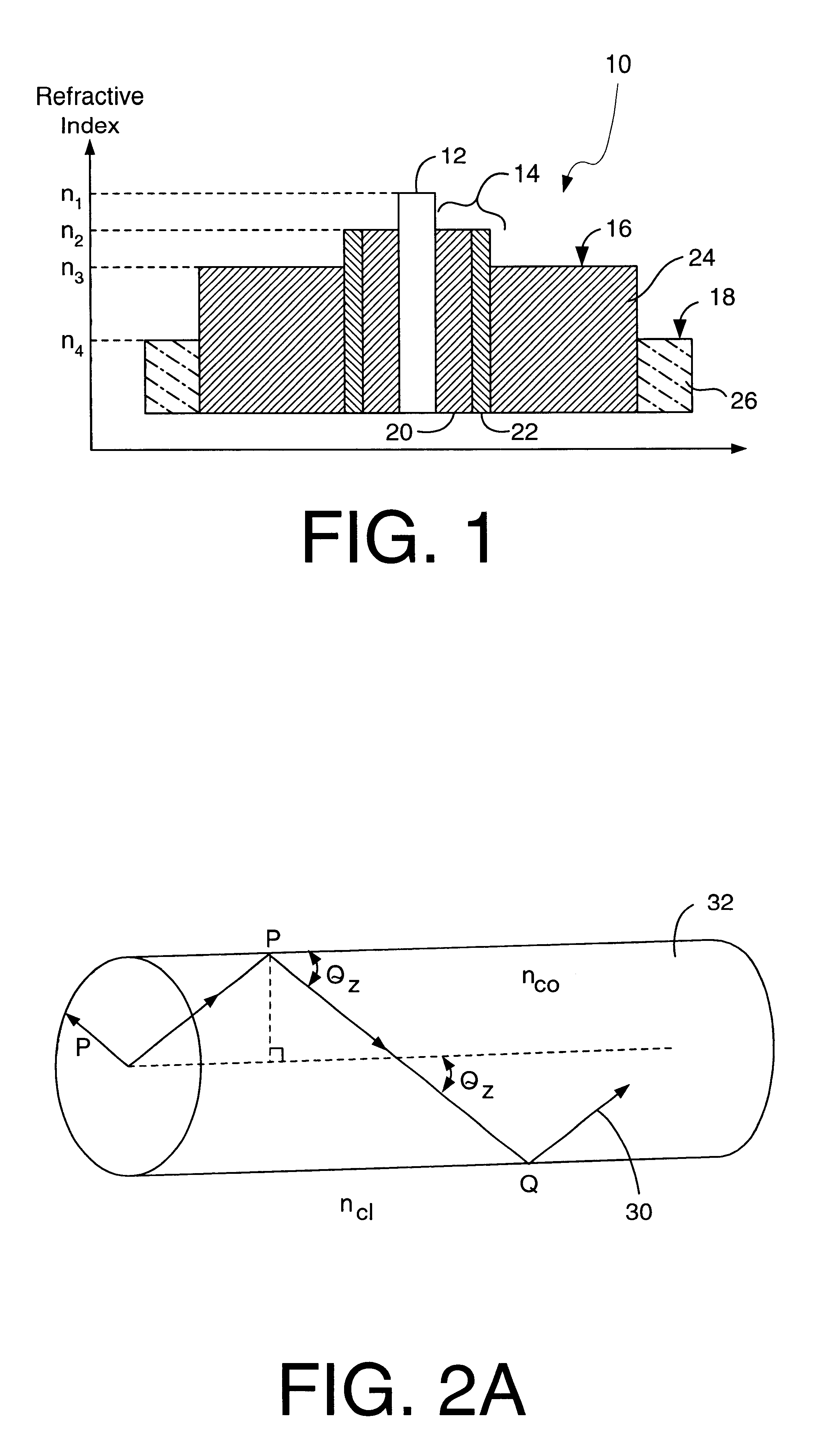
Unfortunately, in YbEr co-doped fibers, the
refractive index of the core is fixed at n.sub.1 =n.sub.silica +0.013 by the phosphorous and
rare earth doping requirements.
Unfortunately, such starting tubes are not readily available, so such an approach is not immediately practical.
However, the fiber is single-mode only in that there is only one guided core mode and that its n.sub.eff is sufficiently different from the other
modes that any direct form of
mode coupling is unlikely.
The fact that some of these
modes have appreciable overlap with the core 12 can complicate the performance of an
amplifier using this fiber.
One potential difficulty created by the higher order guided
modes is
coupling loss.
Nonetheless, fiber misalignments and imperfections will always result in some power being coupled into other guided modes.
In an amplifier, these modes are likely to experience appreciable
gain.
The difficulty with this is that the amplified pedestal signal can be remixed with the fundamental mode signal by imperfections in the output splice.
This has the potential for introducing multipath distortions into the optical signal, something that is usually intolerable in, for example, a video
system.
Other problems, such as
gain depletion by
cladding mode ASE, may also occur, but they are likely to be less significant than multipath signal
distortion.
The choice of
dopant is limited by the need for transparency at 950 nm.
However, any further increase in the pedestal
diameter would result in a group of modes with greatly reduced core interactions.
This solution may not be possible for the
waveguide modes, where a much larger
waveguide area is required.
This is not ideal because the remaining 75% of the modes have minima at the center and will not be absorbed without additional
mode mixing.
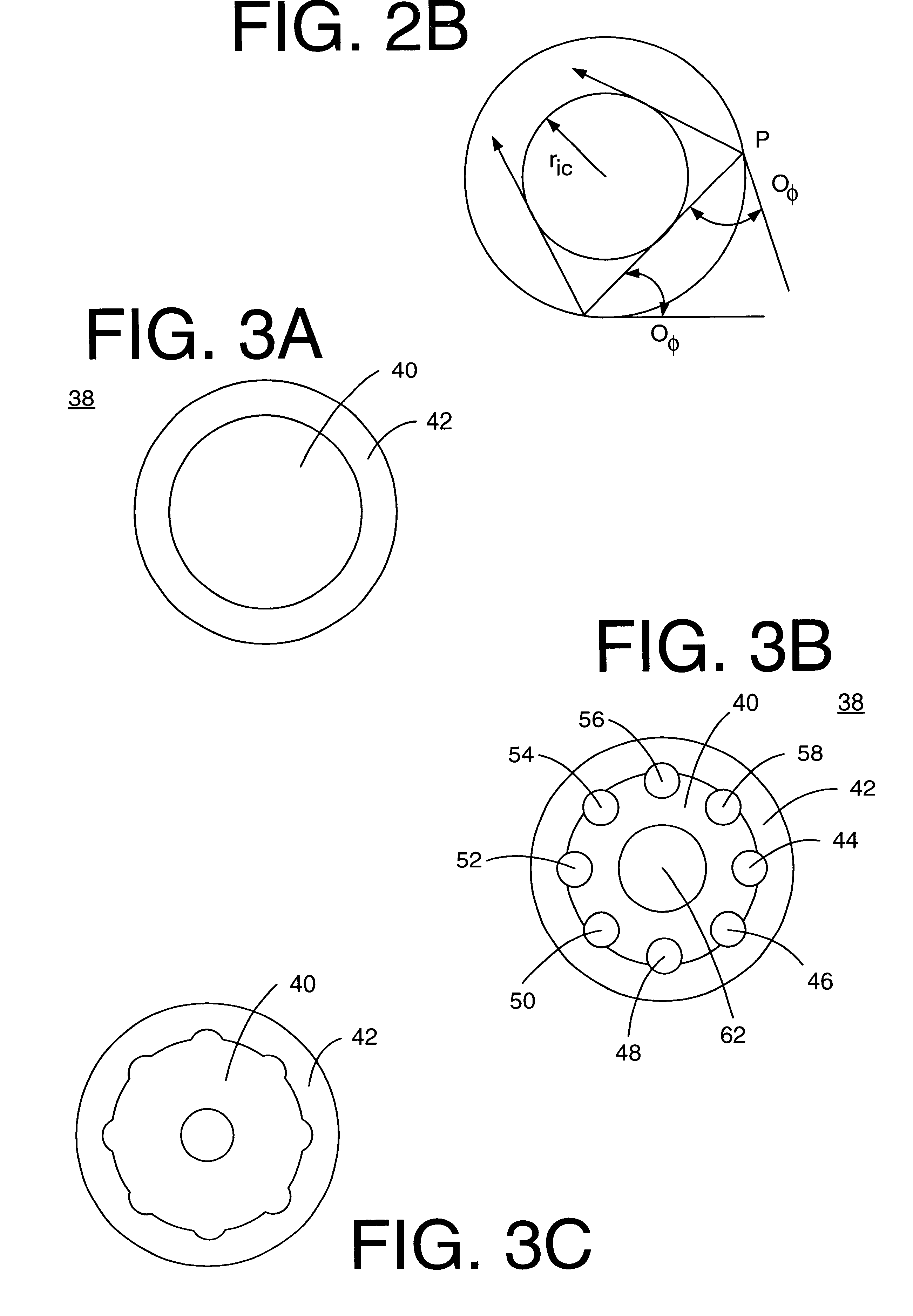
This perturbation approach is impractical for all but very small values of .
delta.r(.phi.) because it requires detailed enumeration of all the modes of the fiber.
Polygons are not especially well adapted to the problem of making all-silica nearly-round fibers with small values of .
delta.r.sub.max.
The problem with this shape is fabrication.
The equivalent fabrication process for an octagon is greatly complicated by the larger number of sides to be ground.
It is also difficult to make all-silica polygonal fibers, since there is no readily apparent process analogous to the low-index organic
coating that produces a conforming low index silica cladding.
Unfortunately, the gas-phase
etching technique is best suited to a two or three lobe figure, and it would be quite difficult to fabricate the more-efficient shapes with larger values of n. Alternative shapes that are more readily fabricated would be desirable.
On the other hand, prior art fibers including elliptical, rather than quasi-circular, boundaries between core and cladding
layers or between two cladding
layers can be extremely difficult to process using conventional equipment, rendering such prior art fibers impractical for use, especially in volume applications.
The values in parentheses, ( ), cannot be fabricated by rod-in-tube methods due to interference between adjacent rods.
Unfortunately, there are limits to the size and number of holes that can be made.
Other potentially efficient combinations are not even shown because they require an impractically large number of holes.
More elaborate (and costly) fabrication techniques can be imagined in which one set of rods is inserted and the preform fused before a second set of holes are made, but such techniques may well be impractical.
The sharper peaks of FIG. 4C cause stronger deflections, but it is believed that the greater number of rays deflected by the broader peaks of FIG. 4D result in the difference in efficiencies of the two shapes.
There are some limitations to this technique, however.
The index changes will produce lensing analogous to that produced by the rod lenses, although shapes of the index distortions are unlikely to be conveniently round and lens-like, so the exact deflections will be difficult to calculate.
The magnitude of the index changes that can be achieved by stress is quite small, as distortions large enough to change the
material density appreciably also tend to cause fracture in a brittle material like glass.
Thus, it is unlikely that the perturbations achieved by this technique will be as effective as those created by the reflective technique.

