Method for generating a highly reactive plasma for exhaust gas aftertreatment and enhanced catalyst reactivity

Inactive Publication Date: 2002-07-23
THE UNITED STATES AS REPRESENTED BY THE DEPARTMENT OF ENERGY
View PDF17 Cites 21 Cited by
  • Summary
  • Abstract
  • Description
  • Claims
  • Application Information

AI Technical Summary

Benefits of technology

Accordingly, it is an object of the present invention to provide a method of non-thermal plasma aftertreatment of exhaust g

Problems solved by technology

While the efficiency of non-thermal plasma treatments may be limited by any of several factors; two limitations that especially inhibit efficient utilization of non-thermal plasma discharge in connection with the aftertreatment of exhaust gases are low electrical efficiency and an undesirable reaction pathway.
However, for non-thermal plasma densities, there occurs considerable plasma shielding of the applied fields, even in the collision dominated regime and field limits.
This space charge shielding is due to the charge imbalances arising within the plasma because of the hig

Method used


Image

  • Method for generating a highly reactive plasma for exhaust gas aftertreatment and enhanced catalyst reactivity
  • Method for generating a highly reactive plasma for exhaust gas aftertreatment and enhanced catalyst reactivity
  • Method for generating a highly reactive plasma for exhaust gas aftertreatment and enhanced catalyst reactivity

Examples


example

The plasma generator of the present invention was applied for conversion of NO.sub.x in N.sub.2 The gas concentrations of NO.sub.x were determined by chemiluminesnce (Rosemount model 951) operated in both NO and NO.sub.x mode. NO.sub.2 was calculated from the difference between the two numbers. O.sub.2 was measured with a fuel cell type analyzer (Illinois Instruments Model 2560).

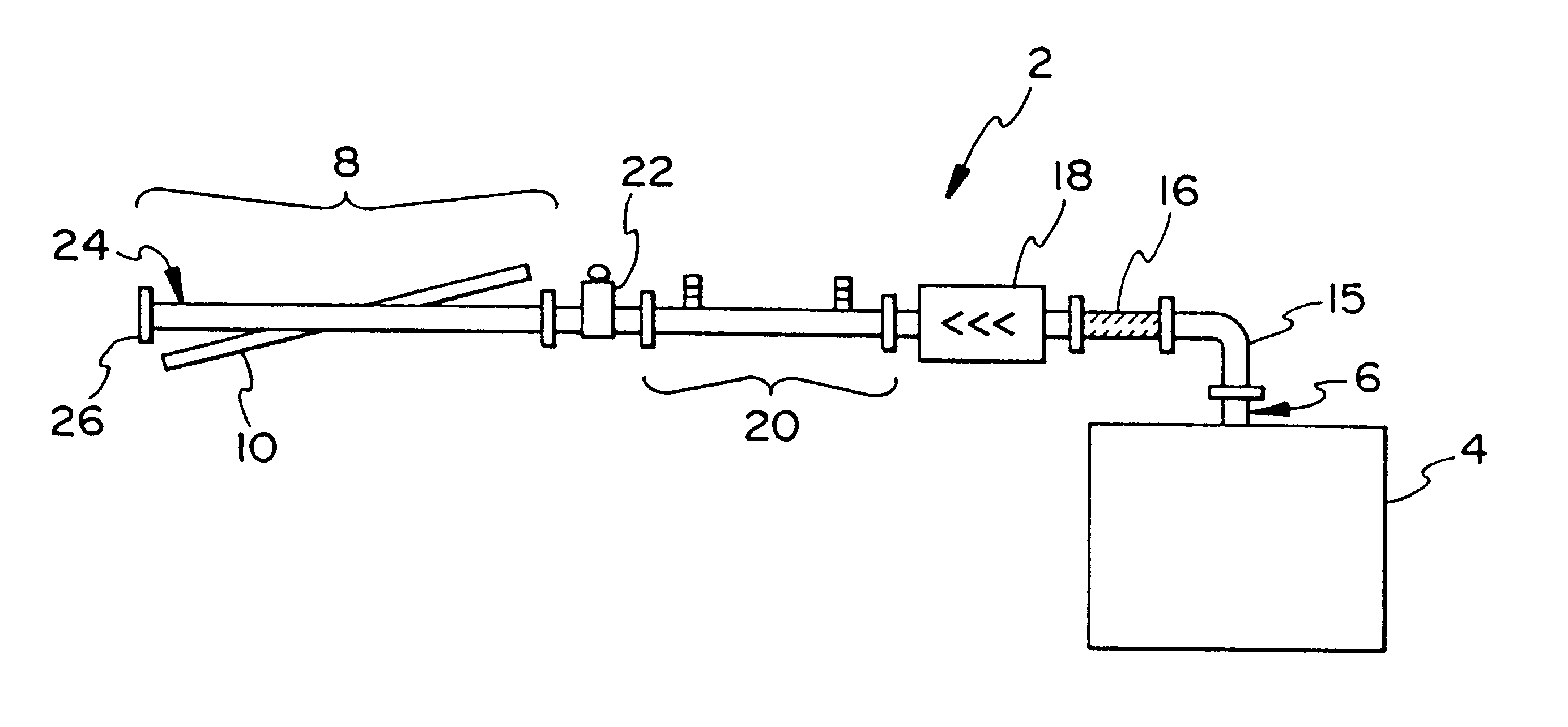
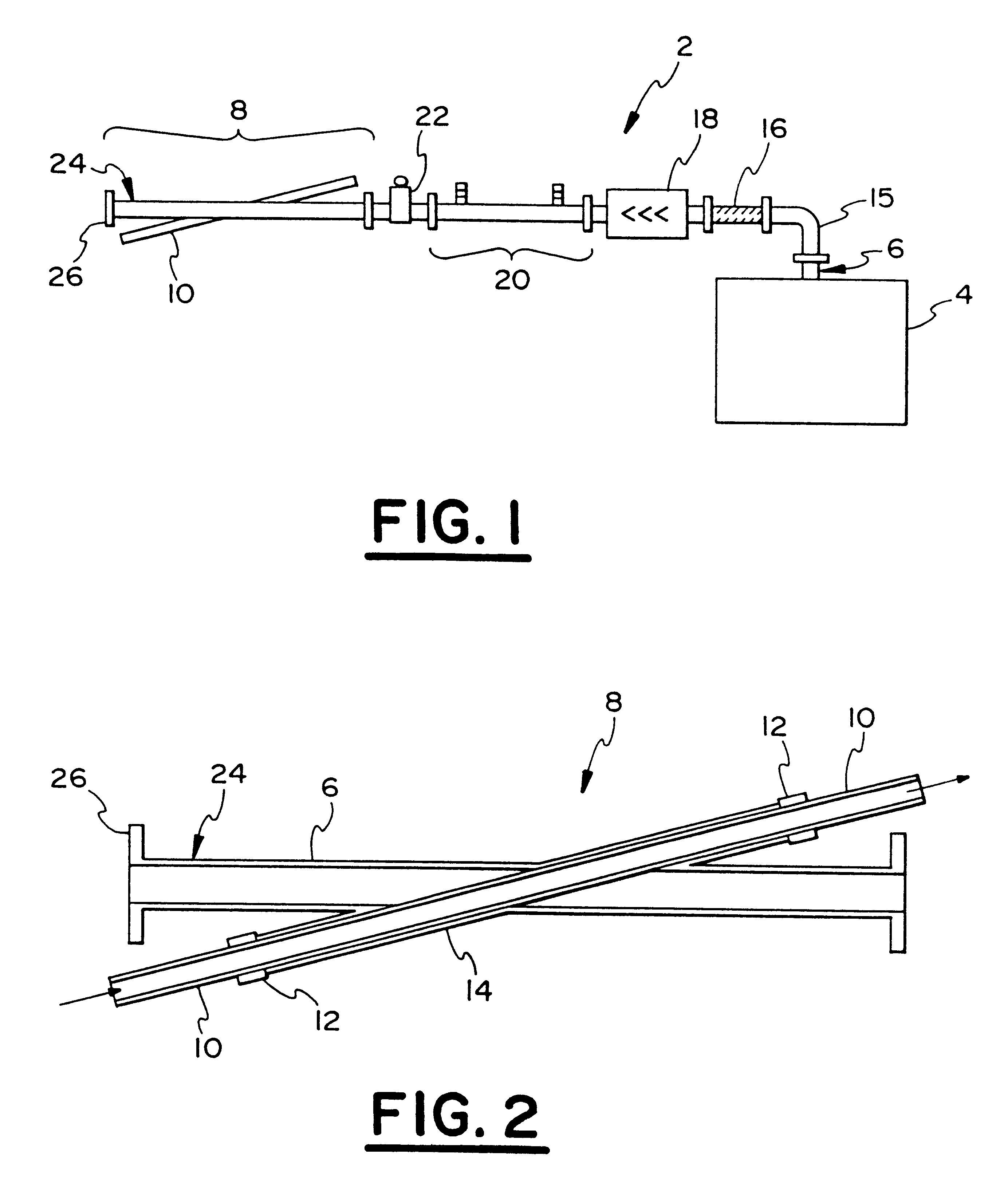
The example was conducted with the above-described waveguide reactor for treatment of a mixture of NO in N.sub.2. Initial gas concentration into the reactor was set to 612 ppm with a flow rate of 3.4 Ipm. This resulted in a residence time of 3s in the entire tube, or a space velocity of 1200 h-1 and represented a lower limit of space velocity. In most cases, the discharge is active over a small portion of the tube. Because no H.sub.2 O was present in the gas mixture, the outlet of the reactor was fed directly into the analyzers. The microwave energy was coupled into the coaxial line of the flow reactor by me...


PUM


Abstract

A method for non-thermal plasma aftertreatment of exhaust gases the method comprising the steps of providing short risetime, high frequency, high power bursts of low-duty factor microwaves sufficient to generate a plasma discharge and passing a gas to be treated through the discharge so as to cause dissociative reduction of the exhaust gases and enhanced catalyst reactivity through application of the pulsed microwave fields directly to the catalyst material sufficient to cause a polarizability catastrophe and enhanced heating of the metal crystallite particles of the catalyst, and in the presence or absence of the plasma. The invention also includes a reactor for aftertreatment of exhaust gases.

Description

The present invention relates to exhaust gas remediation and in particular, a method and apparatus for enhancing the reactivity of the material catalysts found within catalytic converters of cars, trucks and power stations.Plasma aftertreatment of exhaust gases has previously been identified as a possible remediation technique since non-thermal plasma can induce a host of new chemical reactions due to electron excitation thereby causing the production of an abundant amount of radicals and excited state molecules. Plasma aftertreatments rely upon the generation of high local electric fields which directly produce energetic electrons. These energetic electrons can influence the chemistry, even in the collision dominated regime, because they do not lose much energy in elastic collisions due to their small mass, but instead bounce around and transfer most of their energy to molecules; either dissociating, ionizing, or otherwise exciting them. This excitation and radical production can c...

Claims


Application Information

Patent Timeline
IPC IPC(8): B01J19/12F01N3/20H05B6/80
CPCB01J19/126F01N3/202H05B6/80B01J2219/0875B01J2219/0892B01J2219/0894B01J2219/1227Y02T10/26Y02T10/12
Inventor WHEALTON, JOHN H.HANSON, GREGORY R.STOREY, JOHN M.RARIDON, RICHARD J.ARMFIELD, JEFFREY S.BIGELOW, TIMOTHY S.GRAVES, RONALD L.
Owner THE UNITED STATES AS REPRESENTED BY THE DEPARTMENT OF ENERGY
Why Eureka
Try Eureka