Apparatus for light amplification

a technology of apparatus and light, applied in the direction of instruments, semiconductor lasers, optical elements, etc., can solve the problems of spectral output subject to temperature drift, unoptimized output, undesirable lack of monochromity of energy output,

Inactive Publication Date: 2002-11-19
CRX TECH LLC +1
View PDF15 Cites 64 Cited by
  • Summary
  • Abstract
  • Description
  • Claims
  • Application Information

AI Technical Summary

Problems solved by technology

While Fabry-Perot lasers are inexpensive to produce, their output is not optimized for many applications.
This undesirable characteristic arises from the energy reflection that occurs at the facet surfaces.
The lack of monochromacity of the energy output is undesirable for many optical networking applications.
Additionally, the spectral output is subject to drift with temperature and other influences.
Consequently, the output is unsuitable for dense wavelength division multiplexing, because of spectral overlap of adjacent DWDM signals.
The output is also not well suited for high-speed fiber optic communications at wavelengths that are displaced from the optical fibers zero chromatic dispersion point, because of signal degradation due to chromatic dispersion.
However, DFB lasers are not easy to manufacture because the techniques required to produce the periodic structure are cumbersome and are not readily reproducible to generate proper parameters.
They are also susceptible to performance variations due to the ref

Method used


Image

  • Apparatus for light amplification
  • Apparatus for light amplification
  • Apparatus for light amplification

Examples


first embodiment

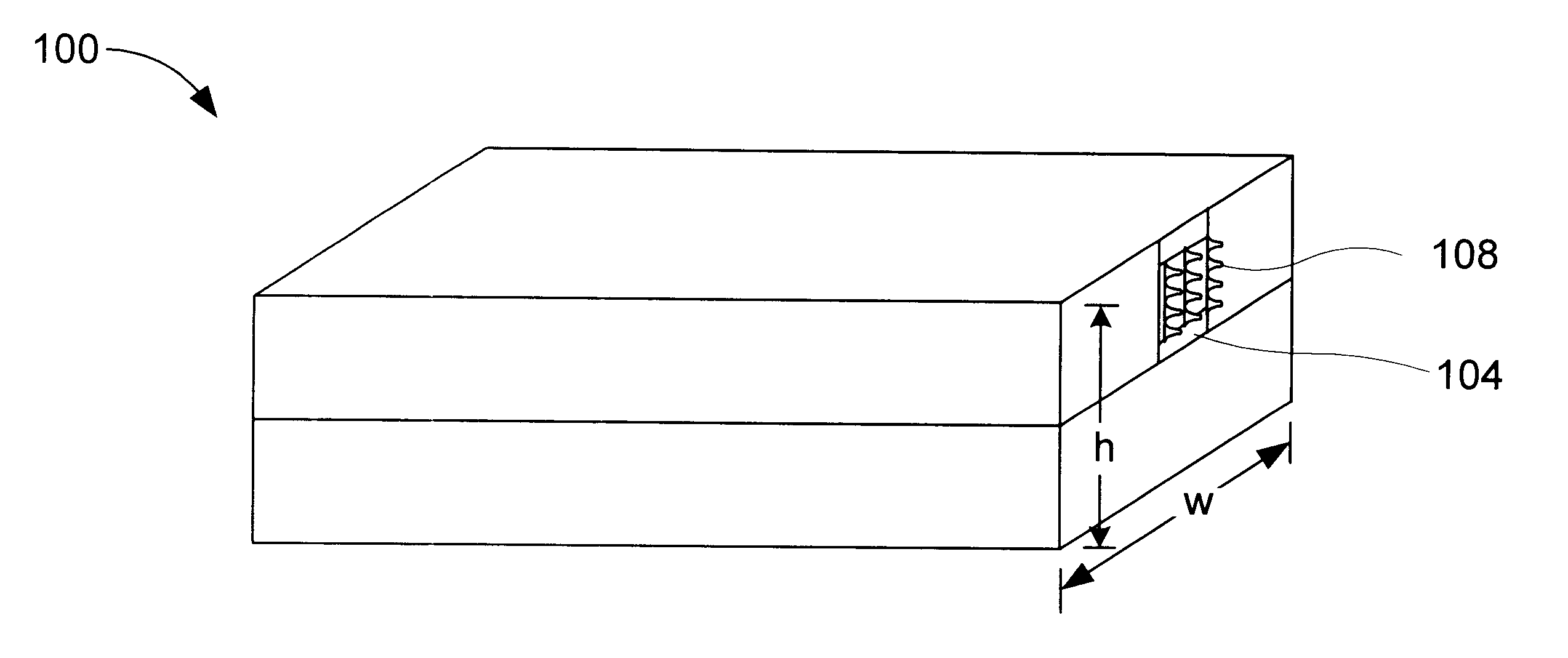
the present invention will be described with reference to FIGS. 1A and 1B. FIG. 1A shows a perspective view of a semiconductor gain device 100 according to an embodiment of the present invention. FIG. 1B shows a cross-section of semiconductor gain device 100. Gain device 100 includes a semiconductor gain medium 102 having a front facet 104 and a rear facet 106. A patterned structure 108 is disposed on front facet 104. An external reflector (shown in FIG. 5), which may be wavelength selective, is typically positioned in front of front facet 104. This reflector in conjunction with the rear facet, defines an optical cavity. Patterned structure 108 may be applied to the facet surface only, as indicated in FIGS. 1A and 1B, or the entire surface structure of the element may be patterned. The entire surface of the facet is the area with height h and width w, as shown in FIG. 1A. In one exemplary embodiment, gain device 100 is a multiquantum well laser, and gain device 100 could operate in ...


PUM

PropertyMeasurementUnit
Nanoscale particle sizeaaaaaaaaaa
Poweraaaaaaaaaa

Abstract

A system for reducing reflection of an optical system can reduce or eliminate reflection at facets of a semiconductor gain medium and can suppress natural longitudinal modes produced within the semiconductor gain medium. In combination with external feedback, the system can allow more precise wavelength control of the light output of a laser, thereby allowing the laser to be used in a dense wavelength division multiplexing system. The system employs a patterned relief surface disposed on a facet of a gain medium. The patterned relief surface may be a "motheye" pattern having a plurality of conical posts disposed on the surface of the facet. The system may be combined with conventional devices, such as a Bragg reflector or a microelectromechanical component, to further improve wavelength control of a resonant optical cavity, thereby improving the operation of optical communications systems.

Description

1. Field of the InventionThe present invention relates generally to the manipulation of light in optical communication networks and fiber optic systems. Particularly, the present invention relates to elements disposed within the light stream of a fiber optic communications network, such as a DWDM network. More particularly, the present invention relates to anti-reflective structures for use in semiconductor lasers and amplifiers.2. Related ArtOptical communication systems are a vital part of today's communication networks. In a typical optical communication system, information-containing optical signals are transmitted along an optical fiber. Lasers are important components of optical communication systems for producing the information-containing signals. Information is modulated upon light signals emitted from the laser into the optical fiber. Initially, optical fibers were used to carry only a single data channel at one wavelength in one direction. Technology, such as wavelength d...

Claims


Application Information

Patent Timeline
IPC IPC(8): H01S5/028H01S5/00H01S5/022H01S5/14H01S5/10G02B1/11
CPCG02B1/118H01S5/028H01S5/02216H01S5/02284H01S5/1082H01S5/14H01S5/141H01S5/02251
Inventor WACH, MICHAEL L.
Owner CRX TECH LLC
Why Eureka
Try Eureka