Optical sensor and method of operation

a technology of optical sensors and optical sensors, applied in the direction of instruments, liquid/fluent solid measurement, analysis using chemical indicators, etc., can solve the problems of sample contamination, complicated handling and disposal of the multitude of individual used test elements, and not without limitations

Inactive Publication Date: 2002-12-03
SIEMENS HEALTHCARE DIAGNOSTICS INC
View PDF79 Cites 186 Cited by
  • Summary
  • Abstract
  • Description
  • Claims
  • Application Information

AI Technical Summary

Problems solved by technology

This aspect also complicates handling and disposal of the multitude of individual used test elements.
While sensors of this type may operate satisfactorily in many applications, they are not without limitations.
Sequential calibration and sample reading may problematically lead to sample contamination in the event the sample chamber and analytical elements are insufficiently washed between samples.
In addition, the calibration is time consuming and may delay analysis of the unknown sample.
This delay may be particularly inconvenient in some operating environments such as, for example, critical care facilities.
An additional disadvantage of the sequential approach is the temporal variation or time delay between testing of the calibrant and testing of the unknown sample.
This

Method used


Image

  • Optical sensor and method of operation
  • Optical sensor and method of operation
  • Optical sensor and method of operation

Examples


example 2

A sensor stripe from example 1 was placed in the measurement device described with respect to FIG. 5 but altered to contain the appropriate yellow LED source, an Omega 585DF20 excitation filter, and a Omega 750DF50 emission filter for the dye octaethyl-Pt-porphyrin ketone. A flowing gas stream with differing partial pressures of oxygen corresponding to 0%, 100%, 26%, 12%, 7%, 12%, 26%, 100% and finally 0% oxygen was passed over the sensor and the luminescence elicited from the dye recorded. The luminescence quenching trace in FIG. 7A was used to derive a Stern-Volmer quenching constant of 0.026 (mmHg).sup.-1. The exposure of the striped oxygen sensing membrane to duplicate aqueous buffer samples tonometered to partial pressures of 92, 43 and 171 mm Hg oxygen also produced rapid, and reversible responses as documented in FIG. 7B which could be used to quantitate the amount of dissolved oxygen in solution.

example 3

A sensing stripe for the analyte oxygen was constructed as follows. The dye octaethyl-Pt-porphyrin was synthesized according to methods described in J. Molecular Spectroscopy 35:3 p359-375 (1970). The styrene / acrylonitrile copolymer, with MW=165,000 and containing 25% acrylonitrile, was obtained from Scientific Polymer Products Inc., Ontario, N.Y. A mixture of 2 mg dye and 100 mg of copolymer dissolved into 1 ml of THF was deposited on a Mylar.RTM. film as in example 1.

example 4

A sensor stripe from example 3 was placed in the measurement device described hereinabove with respect to FIG. 5 and a flowing gas stream with differing partial pressures of oxygen corresponding to 0%, 26% and finally 100% oxygen were passed over the sensor. The luminescence elicited with green 540 nm excitation light from the octaethyl-Pt-porphyrin dye was continuously measured at 650 nm and the luminescence quenching trace recorded as shown in FIG. 8.


PUM


Abstract

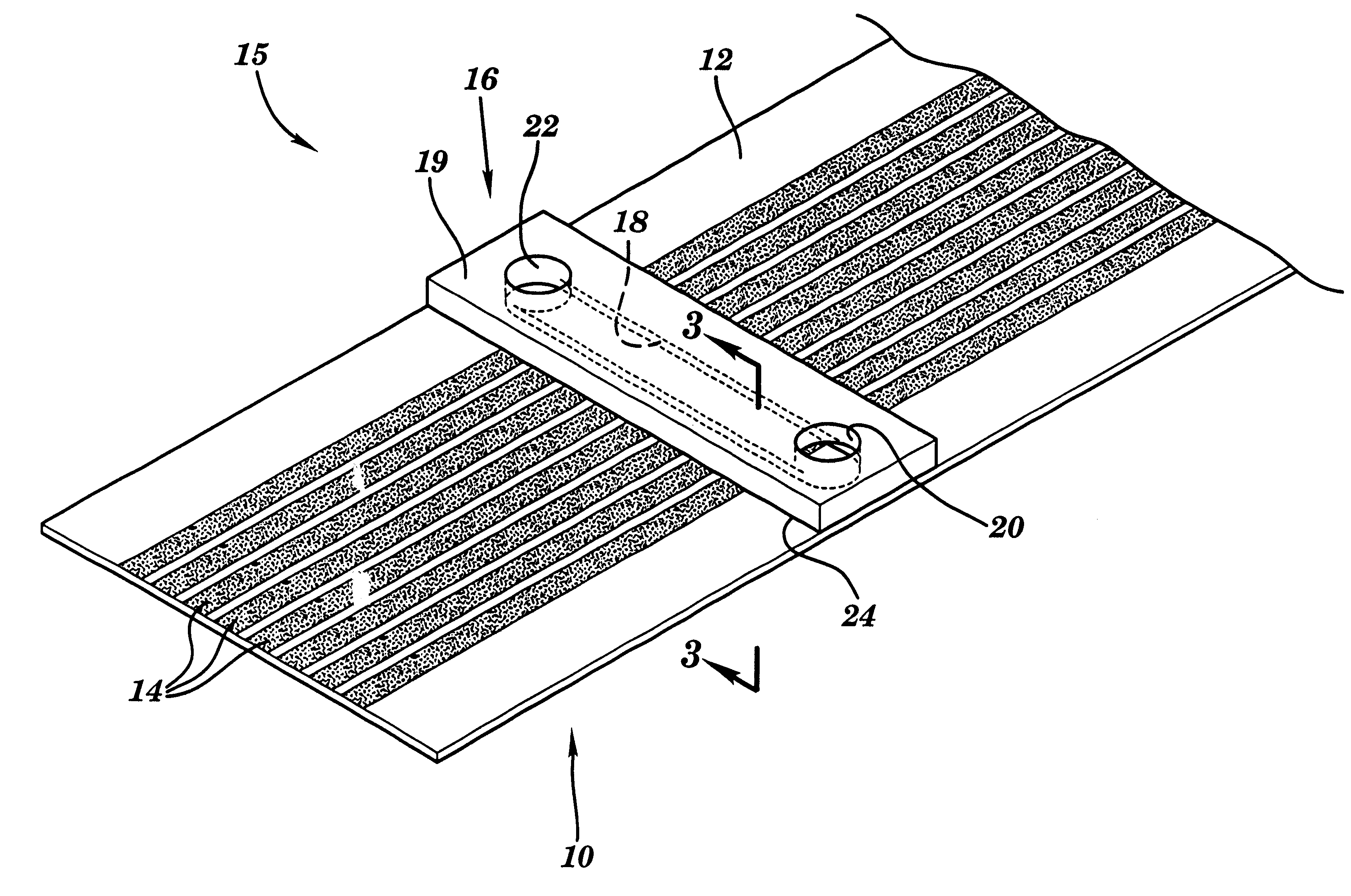
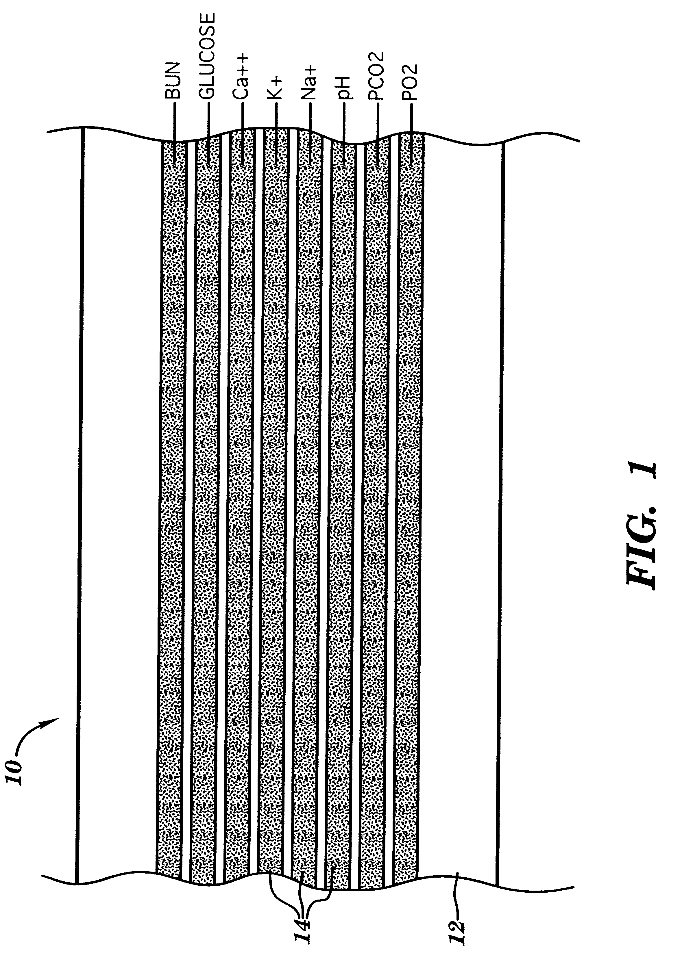
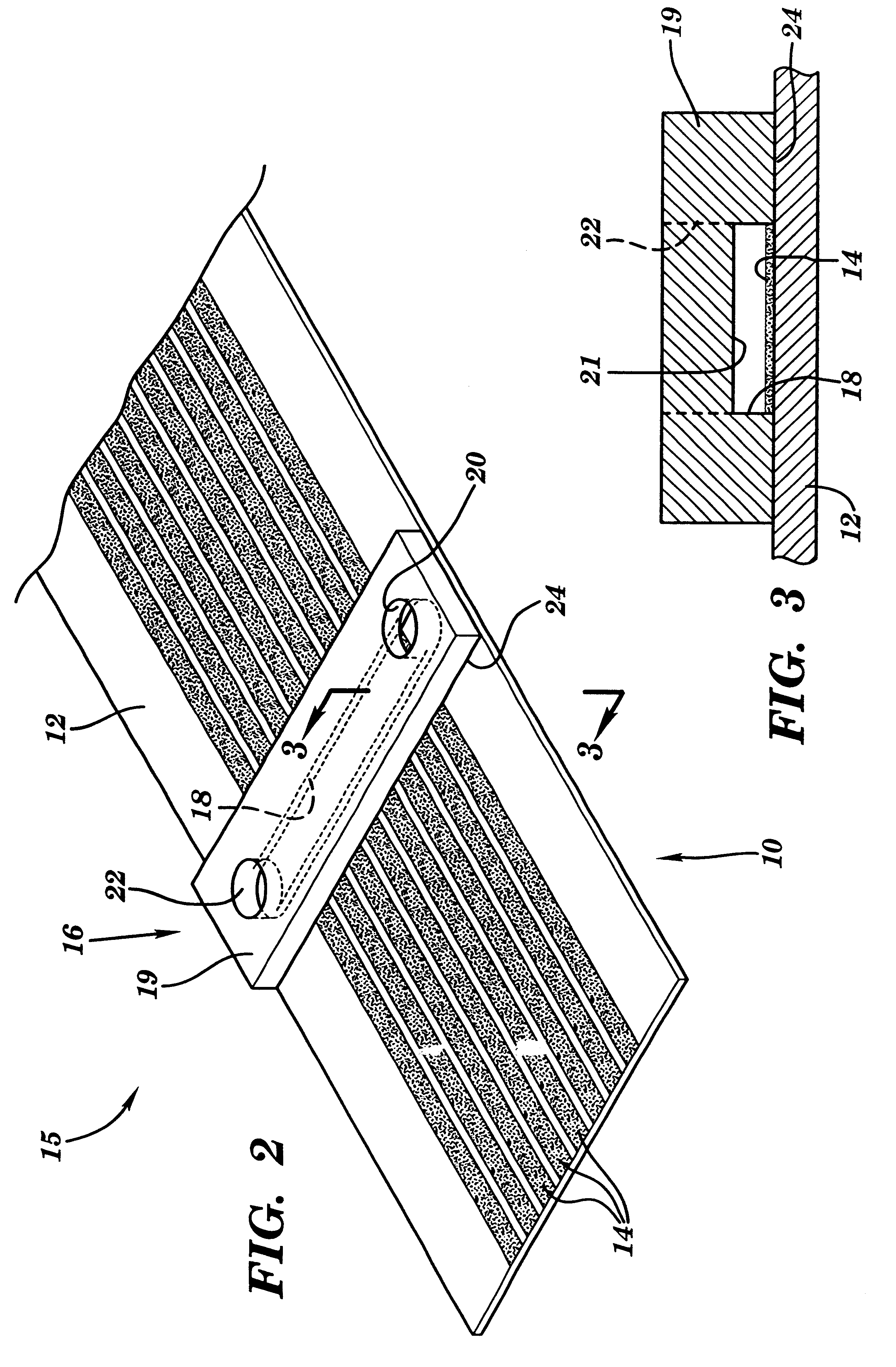
A multiple single use optical sensor includes a series of continuous sensor stripes deposited on a substrate web. At least one sample chamber is adapted to extend transversely across a discrete portion of the series of sensor stripes to facilitate analysis of a sample disposed therein. The sample chamber may be moved, or additional sample chambers provided to enable subsequent measurements of additional samples at unused discrete portions of the sensor stripes. The continuous nature of the sensor stripes provides consistency along the lengths thereof to enable calibration data obtained from one discrete portion of the sensor stripes to be utilized for testing an unknown sample an other discrete portion of the sensor stripes. This advantageously eliminates the need for any particular discrete portion of the sensor stripes to be contacted by more than one sample, for improved sensor performance.

Description

BACKGROUND INFORMATIONChemical analysis of liquids, including biological fluids such as blood, plasma or urine is often desirable or necessary. Sensors that utilize various analytical elements to facilitate liquid analysis are known. These sensing elements have often included a reagent in either a wet or dry form sensitive to a substance or characteristic under analysis, termed analyte herein. The reagent, upon contacting a liquid sample containing the analyte, effects formation of a colored material or another detectable change in response to the presence of the analyte. Examples of dry analytical sensing elements include pH test strips and similar indicators wherein a paper or other highly absorbent carrier is impregnated with a material, chemically reactive or otherwise, that responds to contact with liquid containing hydrogen ion or other analyte and either generates color or changes color. Specific examples of such test strips are disclosed in European publication No. EP 0119 8...

Claims


Application Information

Patent Timeline
IPC IPC(8): G01N21/86G01N21/78G01N33/543
CPCG01N21/8483Y10T436/10
Inventor MASON, RICHARD W.SLOVACEK, RUDOLF E.SULLIVAN, KEVIN J.
Owner SIEMENS HEALTHCARE DIAGNOSTICS INC
Why Eureka
Try Eureka