Non-contact electrical power transmission system having function of making load voltage constant

a technology of non-contact electrical power transmission and load voltage, which is applied in the direction of electric variable regulation, process and machine control, instruments, etc., can solve the problems of increasing the number of parts, the load voltage v0 is remarkably low, and the cost is higher

Inactive Publication Date: 2003-01-07
MATSUSHITA ELECTRIC WORKS LTD
View PDF6 Cites 64 Cited by
  • Summary
  • Abstract
  • Description
  • Claims
  • Application Information

AI Technical Summary

Benefits of technology

It is an object of the present invention to provide an inexpensive non-contact electrical power transmission system...

Problems solved by technology

However, in a non-contact electrical power transmission system provided with the above-mentioned matching capacitor, a problem exits in that for a load whose load current I varies largely, the load voltage V0 lowers remarkably compared with a case where no matching capacitor is provided.
However, providing such a feedback control circuit and a stabilizing source circuit causes the number of parts to increase ...

Method used


Image

  • Non-contact electrical power transmission system having function of making load voltage constant
  • Non-contact electrical power transmission system having function of making load voltage constant
  • Non-contact electrical power transmission system having function of making load voltage constant

Examples


second embodiment

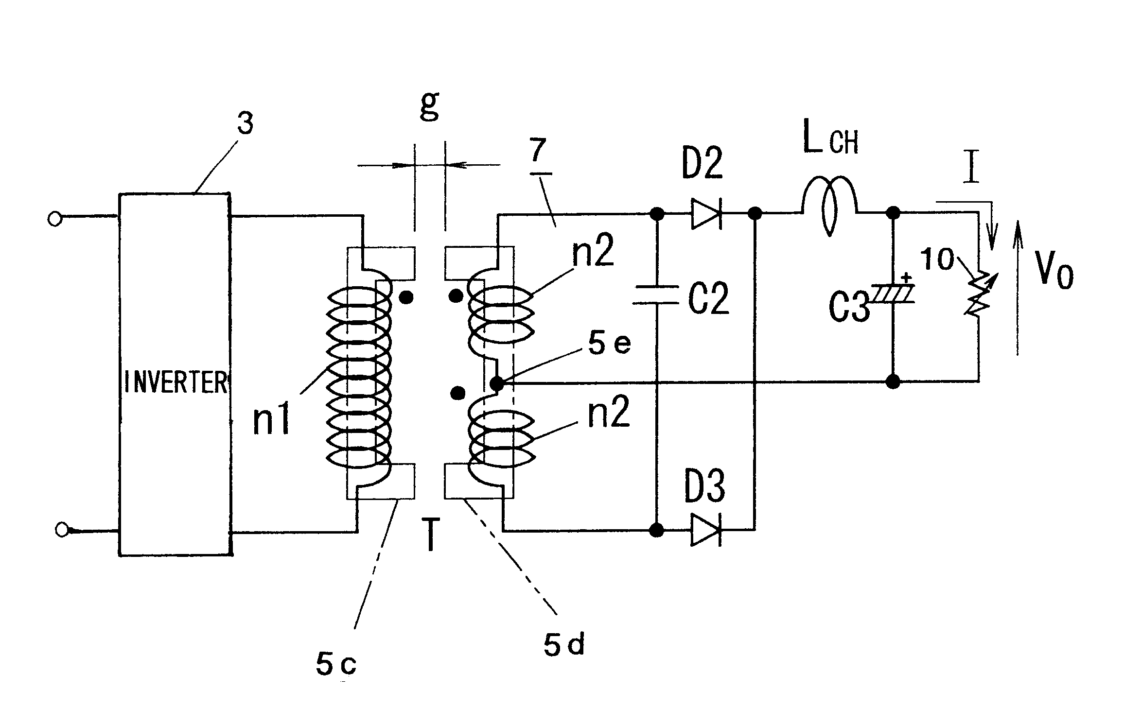
FIG. 7(A) shows a circuit of the non-contact electrical power transmission system in accordance with this embodiment. This non-contact electrical power transmission system has the same configuration as that of the first embodiment shown FIG. 1. However, the circuit in FIG. 7(A) differs from the circuit in FIG. 1 in that the circuit in FIG. 7(A) uses a rechargeable battery as a load 10 connected between output terminals and is utilized as charging device for recharging the rechargeable battery. Components similar to those in the first embodiment are accorded the same reference numerals to omit their explanation. Where a constant-voltage load such as the rechargeable battery is connected as a load 10, the characteristics expressing the relationship between the capacitance of the matching capacitor C2 connected parallel to the secondary winding n2 and the load current I has a trend as shown in FIG. 8. In the characteristics, the capacitance of the matching capacitor C2 when the load cu...

third embodiment

FIG. 18 shows a circuit of the non-contact electrical power transmission system in accordance with this embodiment. While the drive circuit 3 in the circuit described in the second embodiment shown in FIG. 17 is a separately-excited half-bridge type inverter, the drive circuit 3 in the non-contact electrical power transmission system of this embodiment consists of a self-excited partial oscillation converter. This embodiment does not require the provision of a separate control circuit including an oscillation circuit for turning on / off voltage-drive type switching elements S1 and S2 such as MOSFETs. The configuration of the transformer T, and the configuration of the rectifier circuit 7 for rectifying the output of the secondary winding n2 thereof are similar to those of the second embodiment.

In the drive circuit 3, the serial circuit of a pair of capacitors Ca, Cb, and the serial circuit of the switching elements S1, S2 consisting of a pair of power MOSFETs are connected parallel t...

fourth embodiment

The basic configuration of the non-contact electrical power transmission system according to this embodiment is substantially the same as that of the first and second embodiments. The system has features in that as shown in FIG. 22, it uses a push-pull type inverter as a drive circuit 3 for supplying the high-frequency AC voltage to the primary winding n1 of the separable transformer T.


PUM


Abstract

A transformer separable/detachable between a primary winding and a secondary winding, has a capacitor connected parallel to the secondary winding. A high-frequency AC voltage supplied to the primary winding of the transformer generates an induced voltage in the secondary winding. The secondary winding transmits electrical power to a load in non-contact manner. Either the output voltage remains constant as the output current varies, or vice versa. Taking as a first condition a fact that at the time of a maximum load, the time of the reversal of the voltage polarity of the primary winding substantially coincides with the time when an oscillating voltage of the capacitor reaches a maximum or minimum value. Taking as a second condition a fact that at the time of a minimum load, the time of the reversal of the voltage polarity of the above-mentioned primary winding substantially coincides with the time when the oscillating voltage of the above-mentioned capacitor completes one cycle. The capacitance of the capacitor is selected to satisfy simultaneously the first and second conditions. This allows the load voltage to remain constant in a load current range from a minimum to a maximum without requiring a feedback circuit.

Description

The present invention relates to a non-contact electrical power transmission system which includes a transformer with separable primary and secondary windings. The system transmits electric power from the primary side to the secondary side of the transformer in a condition in which a core wrapped with a primary winding and a core wrapped with a secondary winding remain out of contact with each other.Heretofore, in many places, a non-contact electrical power transmission system has been commercially applied. Such systems configure a transformer in which the primary winding and the secondary winding are separable from each other with a core wrapped with a primary winding and a core wrapped with a secondary winding. The system transmits power from the primary side to the secondary side by electromagnetic induction with the primary core and the secondary core remaining out of contact with each other.However, in most conventional non-contact electrical power transmission systems, a load ...

Claims


Application Information

Patent Timeline
IPC IPC(8): H02M3/22H02M3/24H02M3/338H02M1/096H02M3/335H02M3/337
CPCH02M1/096H02M3/22H02M3/338H02M3/337H02M3/335H02J50/10H02J7/00712H02M3/33571H02M3/01
Inventor ABE, HIDEAKI
Owner MATSUSHITA ELECTRIC WORKS LTD
Why Eureka
Try Eureka