Digital rotor flux observer

a digital rotor and flux observer technology, applied in the direction of motor/generator/converter stopper, dynamo-electric gear control, dynamo-electric converter control, etc., can solve the problem of numerical instability, low euler integration method, etc. problem, to achieve the effect of high rotor speed, and simple euler integration method implemented in equation (3)

Inactive Publication Date: 2003-01-21
FORD GLOBAL TECH LLC
View PDF16 Cites 27 Cited by
  • Summary
  • Abstract
  • Description
  • Claims
  • Application Information

AI Technical Summary

Problems solved by technology

While position sensors have been widely used for sensing the rotor position, they can be unreliable, are relatively noisy, and are relatively expensive.
where T is a sampling period, can b...

Method used


Image

  • Digital rotor flux observer
  • Digital rotor flux observer
  • Digital rotor flux observer

Examples


Embodiment Construction

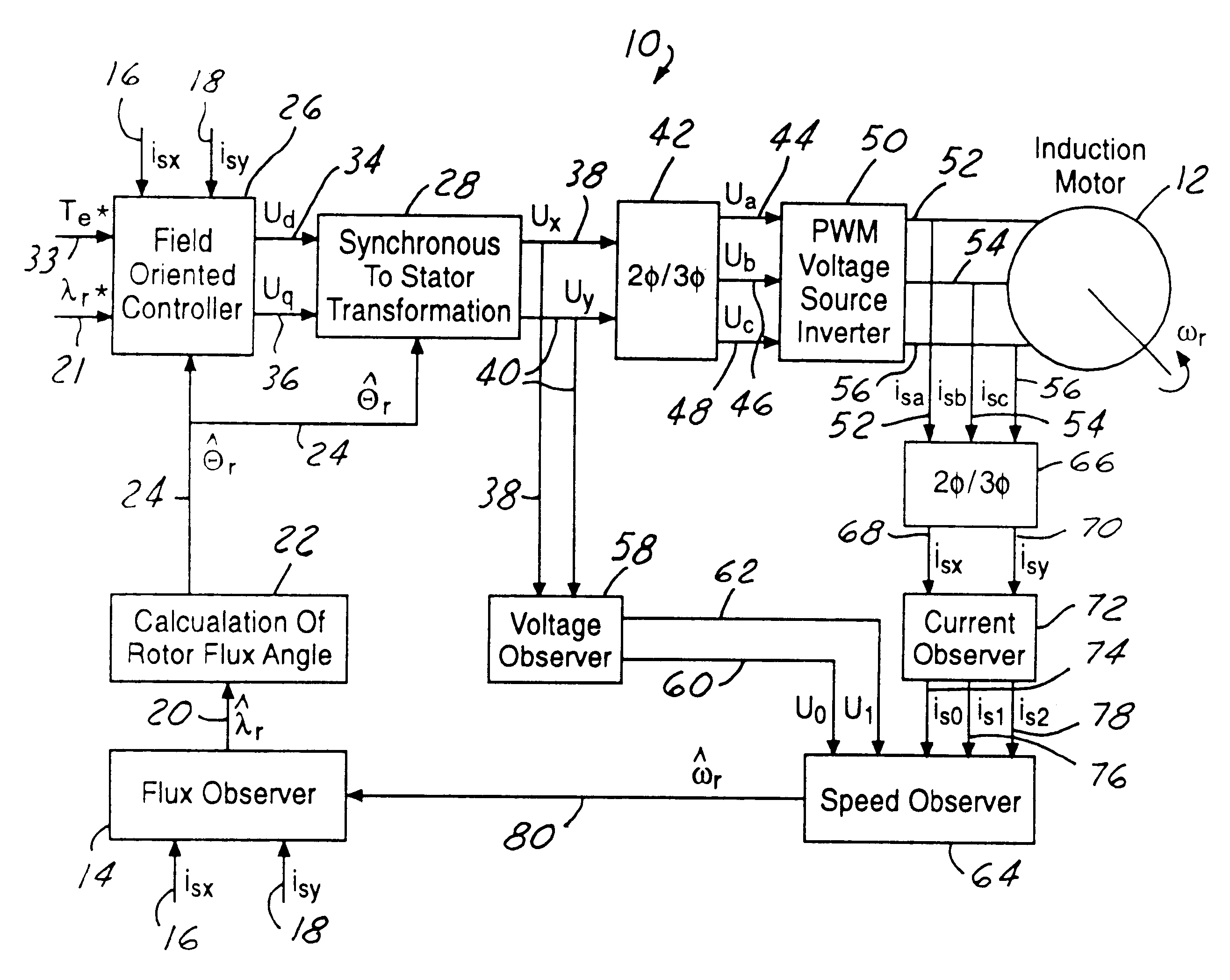
Referring now to FIG. 1, which illustrates a sensorless field orientation control system 10 in accordance with the present invention. The components of the control system 10, which are used to control the torque of an induction motor 12, are briefly and generally described below, as the basic configuration is well known. It should be understood that the control system 10 is merely exemplary and a variety of other components and configurations may be utilized. Further, the induction motor 12 can be incorporated into a variety of applications, including both automotive and non-automotive. An example of an automotive application in which the induction motor 12 can be used is in an electronic power assisted steering system.

For example, as shown in FIG. 1, a flux observer 14 is provided with two current inputs. The first current input (i.sub.sx) 16 is the x component of the stator current while the second current input (i.sub.sy) 18 is the y component of the stator current. The flux obse...


PUM


Abstract

A system (10) for controlling the torque of an induction motor (12) utilizes a flux observer (14). The flux observer (14) receives stator current inputs (16, 18) and a rotor speed estimate (80) and then outputs a rotor flux estimate (20) that provides increased motor control stability at all speeds.

Description

The present invention relates to a system for controlling an electric induction motor and, more particularly, to rotor flux observer design for controlling an electric induction motor.BACKGROUND OF THE PRESENT INVENTIONTypical induction motors include a rotor mounted inside a stator for rotation about a rotation axis. A common rotor design includes a "squirrel cage winding" in which axial conductive bars are connected at either end by shorting rings to form a generally cylindrical structure. The stator is formed by a plurality of winding which surround the rotor and are typically arranged in three separate phases. Time varying voltage is applied across the stator windings which generate an electromotive force (emf) and an associated stator magnetic field which rotates around the stator at a stator field frequency primarily within the space defined by the rotor.As the stator field rotates about the rotor, relative motion between the stator field flux and the rotor bars induces voltag...

Claims


Application Information

Patent Timeline
IPC IPC(8): H02P21/14
CPCH02P21/141
Inventor ZAREMBA, ALEXANDER TIMOFEEVICH
Owner FORD GLOBAL TECH LLC
Why Eureka
Try Eureka