Multiplexed transmission of optical signals

a multi-channel transmission and optical signal technology, applied in the direction of transmission monitoring, coding, instruments, etc., can solve the problems of increasing the number of channels per puls

Inactive Publication Date: 2003-02-18
CIENA
View PDF4 Cites 34 Cited by
  • Summary
  • Abstract
  • Description
  • Claims
  • Application Information

AI Technical Summary

Benefits of technology

It is a further object of the present invention to provide error correction capable of dealing with both failure of individual channels in a multiplexed system and dealing with burst errors affecting a number of successive pulses. It is a further object of the present invention to provide an improved wavelength division multiplexing method with a large number of channels and controlling the stability of individual channel outputs.
It is a further object of the present invention to provide an improved method of generating clock signals when detecting multiplexed signals.
Data transmission is thereby rendered more robust under a range of error conditions such as the onset of failure of one individual channel and also the occurrence of a burst of errors affecting a number of channels simultaneously.
The need for precise alignment of the detector array with any systematic drift in the measurable parameter is thereby avoided, as for example in the case of multiplexing by wavelength division multiplexing where the measurable parameter is optical frequency and the detector array consists of detectors responsive to dispersed frequency components.

Problems solved by technology

This increase in performance cannot simply be accommodated in such systems by increasing the bit rate per channel because of the onset of non-linear effects such as self-phase modulation and because the associated electronic processing at increased serial data rates becomes prohibitively expensive.
Similarly, increasing the number of channels per pulse presents difficulties.
Currently each channel is provided by a separate laser source whose ouptut is filtered to a respective channel wavelength, the wavelengths being separated by guard bands to provide suitable tolerance to drifting due to environmental effects or ageing and, coupled with the limited bandwidth of laser amplifiers used for optical repeating systems, a limitation therefore exists on the number of channels which can be added to expand the data handling capacity of the system.
A disadvantage of this technique is the size of the diffraction grating and associated optics.

Method used


Image

  • Multiplexed transmission of optical signals
  • Multiplexed transmission of optical signals
  • Multiplexed transmission of optical signals

Examples


Embodiment Construction

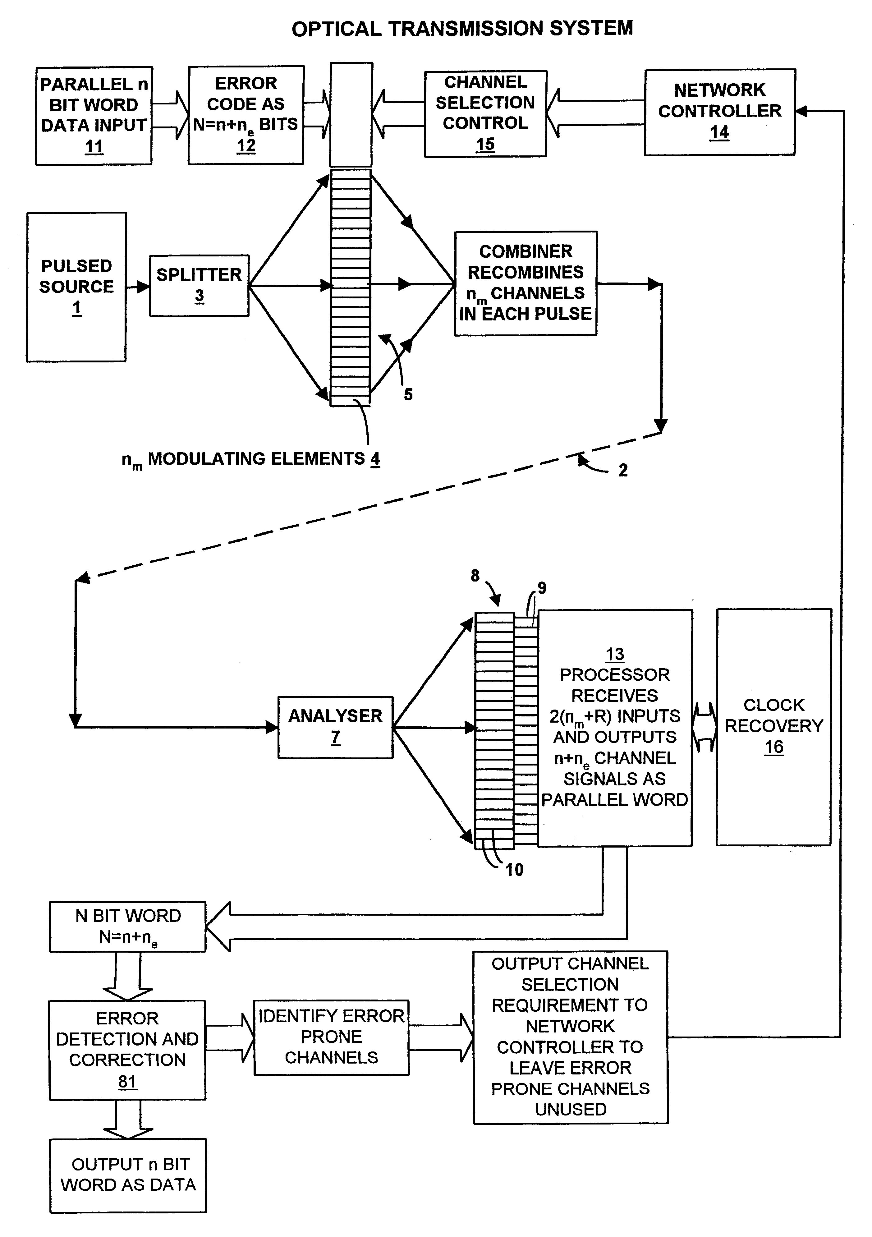
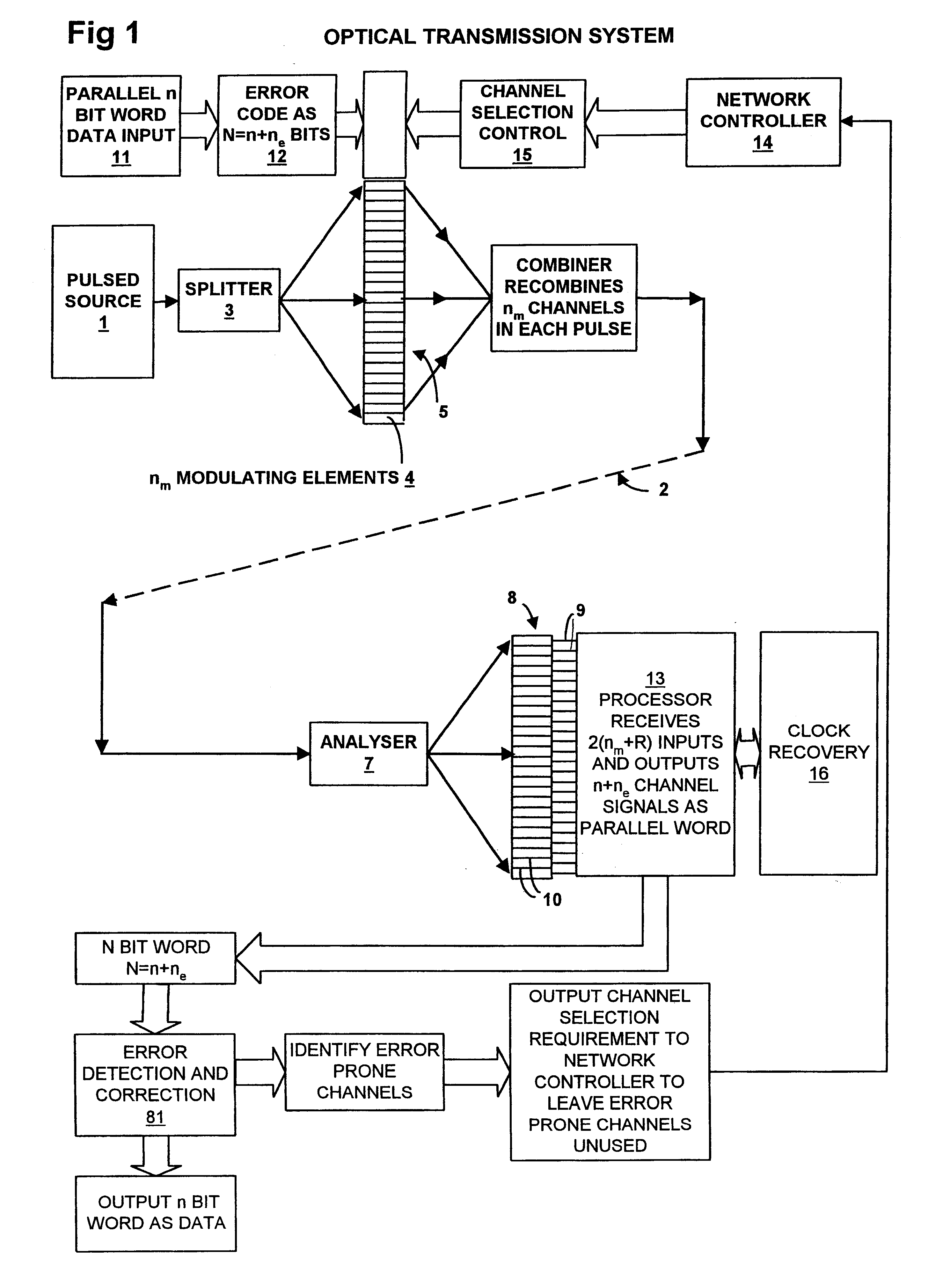
FIG. 1 shows schematically a high-capacity optical transmission system in which optical pulses from a single laser source 1 having a relatively broad bandwidth of 16 nm are subject to a multiplexing process enabling each pulse to carry a large of number of channels. In the present context, the number of channels is used to denote signal carrying capacity of an optical network 2 over which the pulses are transmitted, and, typically, each channel can carry one bit of information per pulse. A data input 11 allows the input of a parallel n bit word, after suitable processing, to be encoded upon the optical pulse by means of the modulator array 5. Such processing may for example include error coding in a forward error coding unit 12 which adds the parity bits to the parallel word.

Pulses from the source 1 are divided by a splitter 3 in a manner suitable for presentation to modulating elements 4 of a modulator array 5. One possible example of a splitter 3 would be a wavelength dispersive e...


PUM


Abstract

In an optical communication system, a train of optical pulses is transmitted such that each pulse carries a set of multiplexed channels. In a receiver, the error rate for each channel is monitored and a subset of channels having the most favorable rate is selected to carry a first data stream. The remaining channels carry a second data stream. Error rate performance is determined on the basis of error detecting codes carried by the channels in the first and second data streams.

Description

This invention relates to high-capacity optical transmission systems in which each optical pulse is multiplexed to carry multiple bits of information.BACKGROUND TO THE INVENTIONExisting telecommunications systems typically transmit optical signals over optical fibres with a pulse rate of 10 Gb / s and, for example, use wavelength division multiplexing to transmit eight channels simultaneously, thereby achieving a data rate of 80 Gb / s per fibre. Transmission of optical signals is possible over about 400 km, using appropriate optical amplifiers, before conversion to the electrical domain is required to effect further regeneration.It is estimated that future requirements of long distance traffic will require a transmission capacity greater than 1 Terabit per second per fibre. This increase in performance cannot simply be accommodated in such systems by increasing the bit rate per channel because of the onset of non-linear effects such as self-phase modulation and because the associated e...

Claims


Application Information

Patent Timeline
Patent Type & Authority Patents(United States)
IPC IPC(8): H04L1/24H04L7/00H04L1/00H04J14/02G02B6/34G02B6/28
CPCG02B6/12011H04L7/0075G02B6/12033H04J14/02H04L1/0041H04L1/0057H04L1/0061H04L1/0064H04L1/22H04L1/24G02B6/12019G02B6/12026G02B6/12028G02B6/2861H04L1/0071
Inventor ROBERTS, KIM BYRONO'SULLIVAN, MAURICE MROBINSON, ALANEPWORTH, RICHARD EDWARD
Owner CIENA
Why Eureka
Try Eureka