
Sliding members and piston for internal combustion engine

a technology of internal combustion engine and sliding member, which is applied in the direction of engine lubrication, cylinders, pressure lubrication, etc., can solve the problems of increasing fuel consumption, coating flakes off or wear, and cannot yield substantial reduction of sliding resistance, so as to achieve the effect of suppressing noise and vibration, narrow clearance between the skirt portion and the sleeve, and effectively avoiding unusual nois

Inactive Publication Date: 2003-02-25
HONDA MOTOR CO LTD
View PDF12 Cites 56 Cited by
  • Summary
  • Abstract
  • Description
  • Claims
  • Application Information

AI Technical Summary

Benefits of technology

to provide sliding members having ideal surface properties after the initial wear. That is, the object of the invention is to provide sliding members in which the sliding is smoothly performed after the initial wear, and an unusual noise can be effectively avoided. Furthermore, another object of the invention is to provide a piston to which the sliding members are applied, so that the clearance between the skirt portion and the sleeve can be narrow, whereby the position of the piston can be stable, and tapping of the piston can be prevented, and noise and vibration are therefore suppressed. It is a further object of the invention to reduce the sliding resistance in an early stage by occurrence of initial wear in a short time in an initial stage of operation.
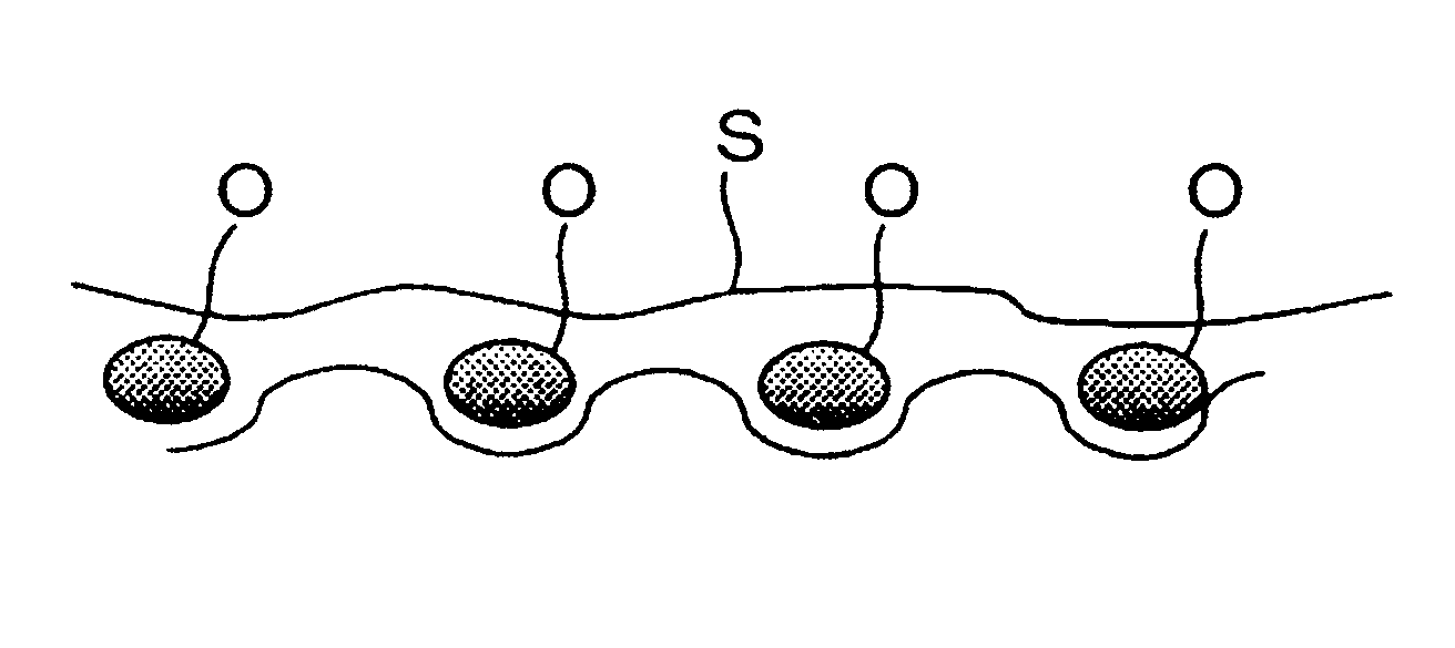
The functions of the dimples in the invention will be explained with reference to FIGS. 5A and 5B. As shown in FIG. 5A, the surface of the piston in the machine-finished state has plural V-shaped grooves extending along the outer circumference thereof when seen magnified. When lubricating oil is provided .to the surface and surface pressure is exerted thereto, the lubricating oil is easily accumulated at the bottom of the groove due to capillary effect rather than the top edge portion, so that an oil film is difficult to be formed and the sliding resistance is large. In contrast, FIG. 5B shows an embodiment of the dimple according to the invention. When lubricating oil is provided to such a surface, as shown in FIG. 5C, the dimple functions as an oil reservoir and accumulates oil droplet O. Therefore, the oil film S is maintained when surface pressure is exerted on the surface, and increase of the sliding resistance is thereby prevented.
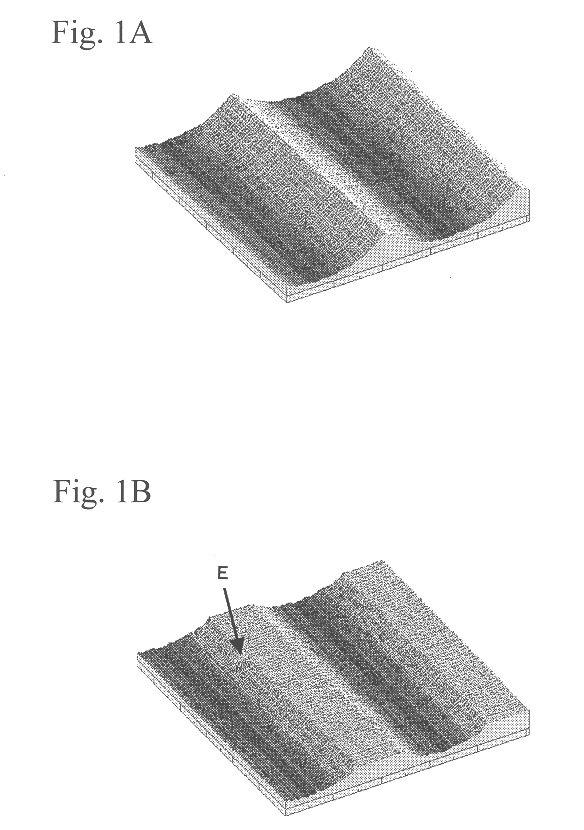
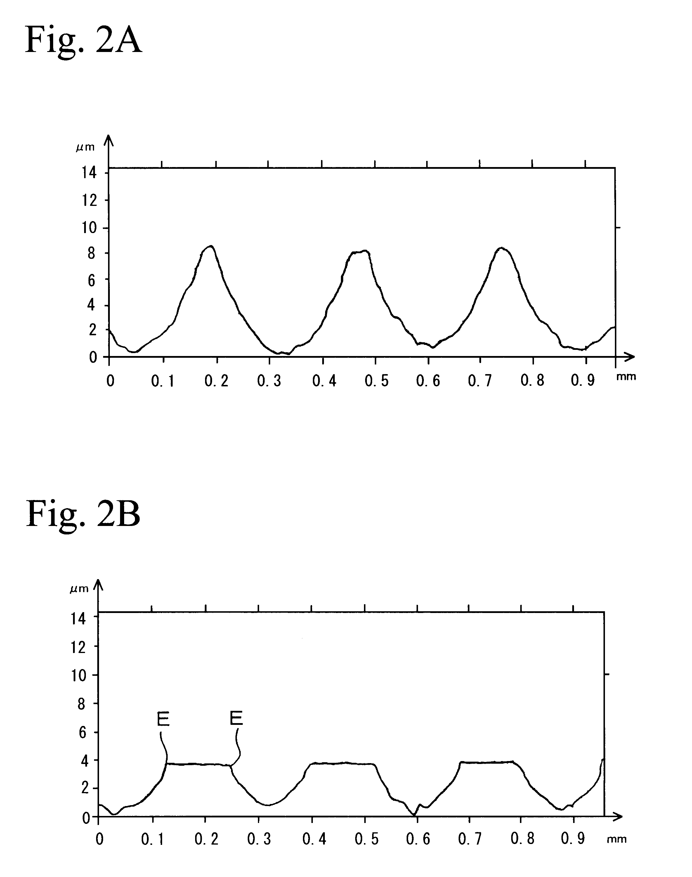
According to the invention, each fine dimple accumulates the lubricating oil, and the lubricating oil can be easily supplied to the sliding surface through the drain portion B by reciprocal movement of the piston. Therefore, after the initial wear has occurred and the piston is fitted to the sleeve, the lubricating oil is supplied to the sliding portion to form an oil film, thereby lubricating the sliding surface and avoiding an unusual noise. FIGS. 4A and 4B are cross sections of the protrusion shown in FIGS. 3A and 3B, wherein FIG. 4A shows the status before the initial wear, and FIG. 4B shows the status after the initial wear. As is shown in FIG. 4A, since the protrusion is formed with dimples, the initial wear occurs rapidly. A running-in phenomenon occurs when several factors such as amount of lubricating oil supplied to the sliding surface, and the surface pressure exerted on the sliding surface are balanced. The balance is obtained in a low sliding resistance since the initial wear is completed in a short time at the initial stage of the operation. Moreover, the lubricating oil is smoothly supplied to the sliding surface and is accumulated in the dimples remaining on the sliding surface, and the sliding resistance after the initial wear can be greatly reduced. Therefore, the clearance between the skirt portion of the piston and the sleeve can be narrow, so that the position of the piston can be stable and tapping of the piston can be prevented, thereby suppressing noise and vibration.
The running-in phenomenon as mentioned in the above should be performed rapidly and with a small amount of wear. The front portion of the protrusion provided along the circumference of the skirt portion which is a sliding surface with a sleeve wears during sliding until the surface pressure becomes stable. The reason of this is that the excessive top portion of the protrusion is removed to maintain a corresponding area of protrusions which can withstand the surface pressure in sliding. The removed top portion remains in the lubricating oil as polishing particles. In order to reduce the amount of the polishing particles as small as possible, it is effective to form beforehand a plane surface which can withstand the surface pressure, rather than forming a sharp edge. Therefore, the protrusion preferably has an approximately trapezoidal portion when viewed in cross section along the sliding direction. In such a design, the surface pressure exerted on the sliding surface and the surface roughness thereof, and the amount of the lubricating oil supplied according to the relative sliding speed, can be stable in a shorter period, as opposed to the case in which a sharp edge is formed by machining.
In the shot peening processing for forming dimples, fine particulate glass beads are preferably projected to the piston by air. The average diameter of the shot is preferably in the range of 20 to 60 .mu.m, and the diameter of the shot is preferably 20 .mu.m or more. The air pressure in the projection of the shot is preferably in the range of 1.5 to 5.0 kg / cm.sup.2. It should be noted that although the dimples can be formed on only the protrusion, it is preferable to form the dimples on the overall surface including the recess. The protrusions and the dimples are preferably formed on not only the skirt portion of the piston, but also grooves for piston rings and a land, so that production of unusual noises between the groove and piston ring and between the land and the sleeve are prevented.

Problems solved by technology

However, the former case cannot yield substantial reduction in sliding resistance, and the later case has problems in that the coating flakes off or wears.
Therefore, if the contact of the skirt portion with the sleeve is not smoothly performed, the sliding resistance increases, whereby the fuel consumption is increased, and an unusual noise is produced due to the contact of the piston with the sleeve in some cases.
It is known that these methods cannot yield the effect of avoiding production of an unusual noise.
In general, it is known that surfaces sliding with respect to each other initially undergo severe wear.
The reason for this is that sharp edges formed by machining are worn initially, and such wear is called "initial wear".
However, when the supply of a lubricating oil or the relative speed of the sliding, or the like, changes greatly, heat generation, rapid wear, and macro deformation of the sliding surface may occur, and these may cause an unusual noise.
In this case, the temperature of the portions would be increased and cause an unusual noise.
When lubricating oil is provided .to the surface and surface pressure is exerted thereto, the lubricating oil is easily accumulated at the bottom of the groove due to capillary effect rather than the top edge portion, so that an oil film is difficult to be formed and the sliding resistance is large.
When the dimples are too small, the function of accumulating the lubricating oil is not sufficient, and the function of extracting the lubricating oil toward the sliding surface is not sufficient since the drain portion is too small.
In contrast, when the dimples are too large, the protrusion is acutely deformed, and the functions by the protrusion cannot be obtained.

Method used


Image

  • Sliding members and piston for internal combustion engine
  • Sliding members and piston for internal combustion engine
  • Sliding members and piston for internal combustion engine

Examples


Embodiment Construction

A. Production of Samples

Pistons having a typical shape and a size were produced. Protrusions (streaks) having a cross section shown in FIG. 6A were formed around the outer circumference of the pistons. The distance between the protrusions was about 250 .mu.m, and the height thereof was about 10 .mu.m. The piston was attached to a turntable, and glass beads having an average diameter of 40 .mu.m were projected to the side surface of the piston by compressed air while rotating the piston. Plural samples were produced while the incident pressure was changed to 5.0 kg / cm.sup.2 from 1.5 kg / cm.sup.2.

B. Measurement of Dimple

For evaluation of the average depth of dimples in each sample, surface roughness Ra of the sample was measured, and the Ra was defined as the average depth. The results are shown in FIG. 7. As will be understood from FIG. 7, the depth of the dimple increases as the incident pressure in shot peening processing is increased.

C. Measurement of Friction Loss

Suitable samples ...


PUM


Abstract

A sliding surface of at least one of sliding members sliding with respect to each other in a sliding direction comprises a protrusion extending along a direction intersecting the sliding direction and fine dimples provided on a surface of the protrusion. In the sliding members, lubricating oil is accumulated in the dimples, and is easily extracted through a drain portion formed by dimple in a running-in operation.

Description

1. Technical FieldThe present invention relates to sliding members which can maintain sufficient amounts of lubricating oil between sliding surfaces of sliding members sliding with respect to each other and which can reduce sliding resistance and can effectively avoid production of an unusual noise therebetween. The present invention also relates to a piston for internal combustion engines, which can hold sufficient amounts of lubricating oil on the sliding surface with a sleeve.2. Background ArtIn order to reduce the sliding resistance of sliding members, fluorine compounds, silicon, or the like, have been added to the materials of sliding members, or alternatively, coatings made from materials such as molybdenum and fluorine resin have been provided heretofore. However, the former case cannot yield substantial reduction in sliding resistance, and the later case has problems in that the coating flakes off or wears.In particular, in a piston for internal combustion engines (hereinaf...

Claims


Application Information

Patent Timeline
Patent Type & Authority Patents(United States)
IPC IPC(8): F02F3/00F16J10/00F16J10/04F01M1/08F01M1/00F16N7/00F16N7/16
CPCF16J10/04F02F3/00F01M2001/083F16N7/16
Inventor KOBAYASHI, SHIGEMIMURATA, MASASHIOGIHARA, HIDEMIYAMADA, HIROSHIISHIZUKA, KAZUHISATSUNASHIMA, SAKAE
Owner HONDA MOTOR CO LTD
Learn More