Device and method for detecting analytes

Inactive Publication Date: 2003-04-15
KNOLL MEINHARD
View PDF14 Cites 266 Cited by
  • Summary
  • Abstract
  • Description
  • Claims
  • Application Information

AI Technical Summary

Benefits of technology

A further advantage of the invention consists in that the current which flows through the small diaphragm opening to the counter-electrode in the measuring solution, only causes a very small current density at the electrode. Compared to using a microelectrode, in this case the current density is smaller by the ratio of the cross-sectional surface area of the diaphragm opening and electrode surface. This results in changes in the electrical resistance being caused mainly by particle-induced field disturbances and the influence of electrochemical electrode reactions is largely negligible. The measurements may be carried out more precisely in this manner.
In accordance with a further exemplary embodiment of the present invention, the measurement of detection of the disturbances to the electric field caused by the marker particles is carried out in the measuring solution using a potentiometric process, wherein the electric field is formed at the surface of an electrode by potential-forming steps at the boundary between measuring solution and electrode.
The advantages of this embodiment consist particularly in that likewise electrodes having greater diameter or greater surface may be used. This can be seen from the fact that the potential-fo

Problems solved by technology

Therefore it has the very high sensitivity or precision possible for the determination of electrical or electrochemical properties and consequently a very low detection limit at high sensitivity.
The production of microelectrodes is indeed known, but it

Method used


Image

  • Device and method for detecting analytes
  • Device and method for detecting analytes
  • Device and method for detecting analytes

Examples


Embodiment Construction

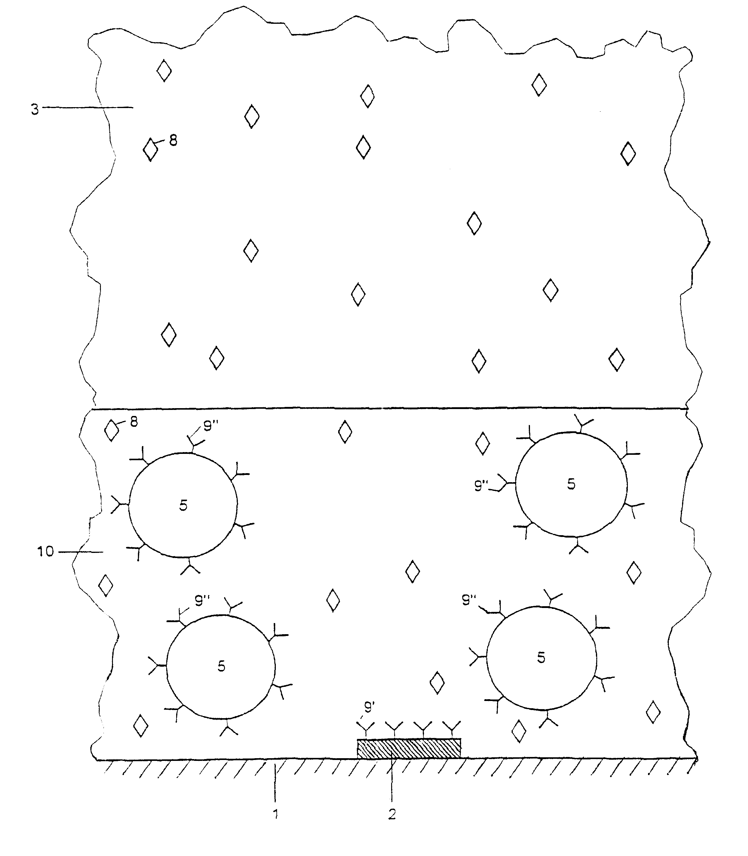
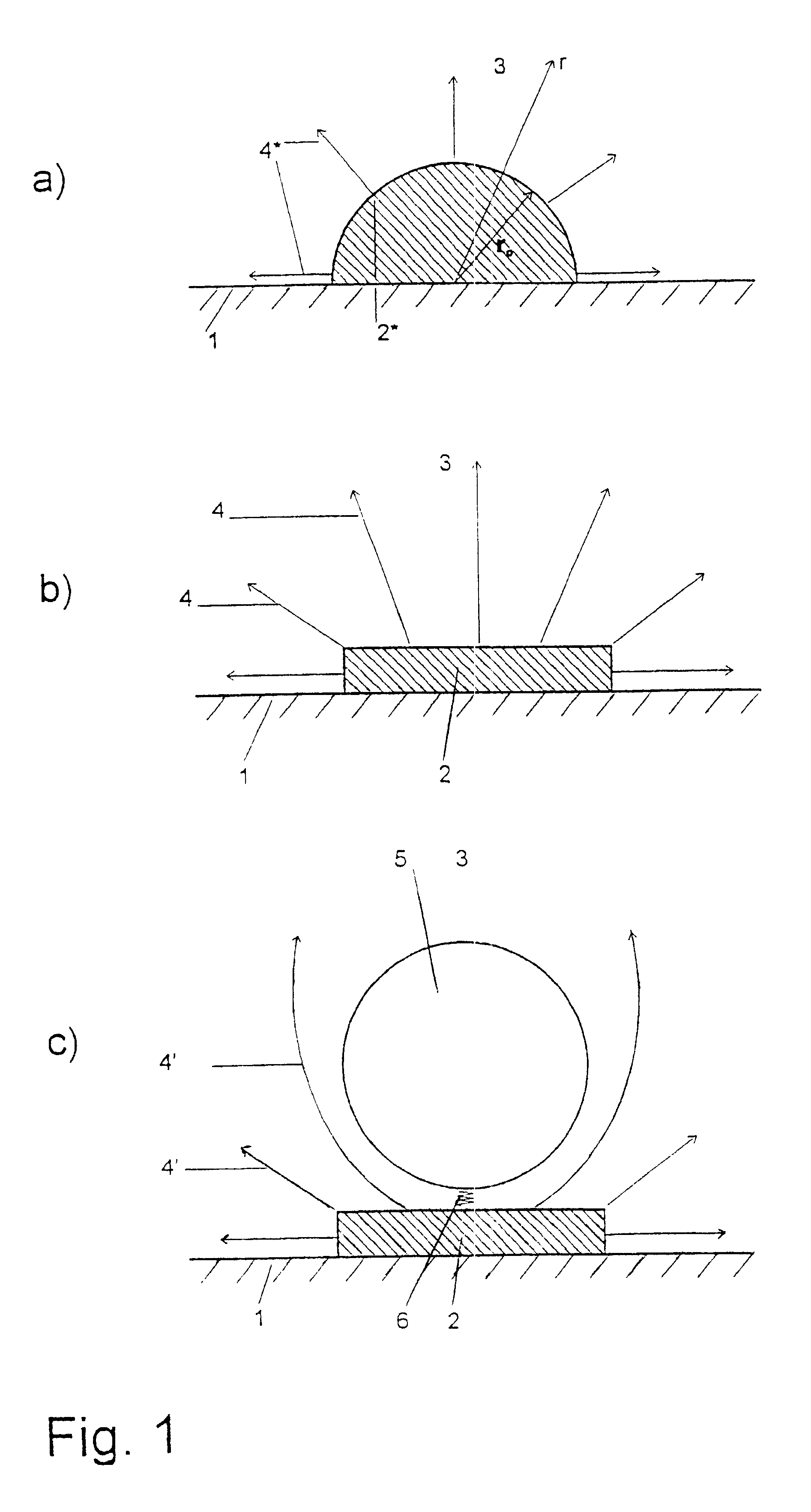
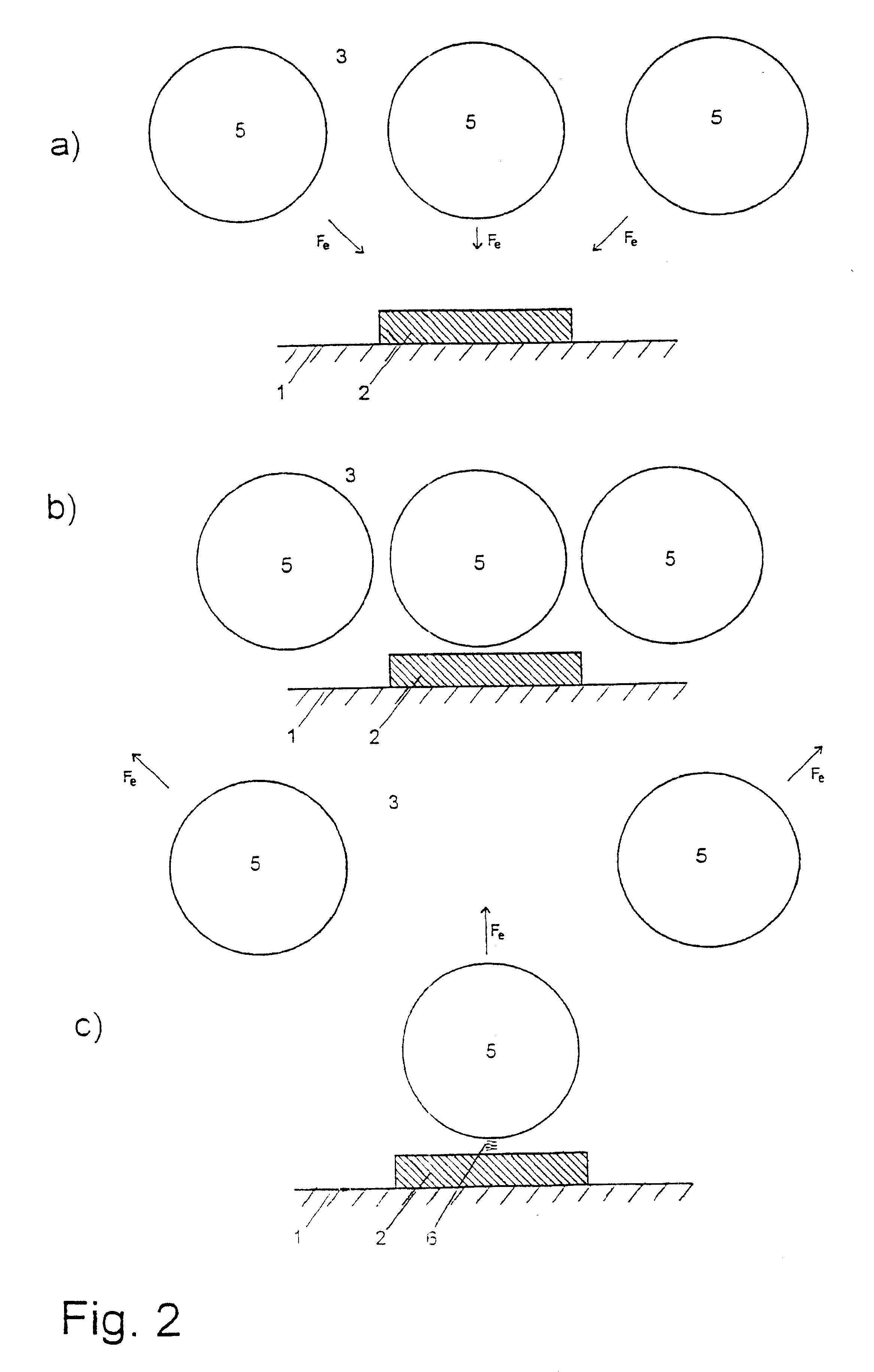
The mechanism of binding detection is described in more detail in FIG. 1.

FIG. 1a) shows the surroundings of a microelectrode. Here 1 is an insulating support, on which a spherical microelectrode 2* is arranged. An electric voltage is applied between this microelectrode 2* and a counter-electrode not shown. Both electrodes are surrounded by a liquid measuring medium 3. Electrical field lines 4 emerge from the live microelectrode 2*. FIGS. 1b) and 1c) show the mechanism of binding detection. The planar microelectrode 2 has square shape having an edge length of 3 .mu.m. The electrode has been produced with the aid of known thin-layer processes on an insulating support 1 which consists of glass. The material of the marker particle is, for example SiO.sub.2, and the diameter is 2 .mu.m.

In aqueous measuring medium, the specific conductivity is described as follows: ##EQU1##

Herein z.sub.i is the charge number, .mu. is the mobility and C the concentration of the ions. F represents the Farad...


PUM

PropertyMeasurementUnit
Diameteraaaaaaaaaa
Magnetic fieldaaaaaaaaaa
Currentaaaaaaaaaa

Abstract

The invention relates to a method for detecting analytes and to a device for carrying out the method, for use for analysis or diagnosis in the fields of chemistry, biochemistry, molecular genetics, food chemistry, biotechnology, the environment and medicine. Marker particles (5) with different electrical properties or a different relative permeability to those of the measuring solution (3) surrounding them are used to detect the analytes (8). The marker particles (5) either bond specifically to the analytes (8) or to a base (2) in competition with the analyte. The analytes (8) are detected by the changes in an electrical field or an electrical current generated by electrodes (2) or in an electrical voltage applied to an electrode or in a magnetic field, said changes being caused by marker particles which have bonded with the analytes or by marker particles which have instead bonded to the base in an electrical field.

Description

1. Field of the InventionThe invention relates to a process for detection of analytes and a device for carrying out the process.Such devices and processes, which are also designated below with the term of assay describing both, serve for qualitative and quantitative recording of specific bonds between at least two molecules. This includes, for example the recording of receptor-ligand interactions, antibody-antigen interaction, recognition of nucleic acids, interaction between oligonucleotides and DNA as well as other molecular interactions. Processes and devices of this type can be used, for example in chemistry, clinical analysis, pharmaceutical development, environmental analysis and in routine molecular biology work including sequencing of nucleic acids.It is known that immunoassays having different detection methods are carried out. This includes radioactive, fluorescence-assisted and chemoluminescence-assisted and enzymatic processes (C. P. Prince, D. J. Newman: Principles and ...

Claims


Application Information

Patent Timeline
IPC IPC(8): C12Q1/68G01N33/543G01N33/58G01N27/416
CPCG01N33/587C12Q1/6825G01N33/5438B01J2219/005B01J2219/00585B01J2219/00596B01J2219/00605B01J2219/00612B01J2219/00614B01J2219/00648B01J2219/00653B01J2219/00659B01J2219/00702B01J2219/00637
Inventor KNOLL, MEINHARD
Owner KNOLL MEINHARD
Why Eureka
Try Eureka