
Method and apparatus for treating aqueous medium

a technology of aqueous medium and treatment method, which is applied in the direction of water treatment multi-stage treatment, crystal growth process, disinfection, etc., can solve the problems of large electricity required for the treatment, inability to treat squander liquor at sufficient efficiency by conventional hydrothermal reaction process, and difficulty in increasing the area of electrodes in the reaction vessel

Inactive Publication Date: 2003-06-03
EBARA CORP
View PDF20 Cites 33 Cited by
  • Summary
  • Abstract
  • Description
  • Claims
  • Application Information

AI Technical Summary

Problems solved by technology

However, waste liquors could not be treated at sufficient efficiency by conventional hydrothermal reaction processes.
Although this hydrothermal electrolytic reaction is useful as a process for very effectively degrading reducing substances, later studies revealed that a large electricity is required for the treatment of waste liquor.
However, it is not always easy to increase the area of electrodes in a reaction vessel, which should be exposed to high temperature and high pressure of hydrothermal electrolytic reaction.
Therefore, how to increase the electrolytic current in a limited electrode area was a great issue for increasing the throughput in said treatment process.
However, the generation of a hypohalite ion was scarcely detected during electrolysis at high temperature.
However, nascent oxidizers or active oxygen electrochemically produced in the reactor entail higher production costs as compared with normal oxidizers (external oxidizers), though they have high activity.
When these readily degradable substances or electrolytically degradable ammonia or various organics exist at the hydrothermal electrolytic reaction site, they consume nascent oxidizers or active oxygen to increase power consumption of the hydrothermal electrolytic reactor.
High-activity electrochemical oxidizers internally produced in hydrothermal electrolytic reaction are consumed to degrade not only persistent substances but also readily degradable substances or electrolytically degradable ammonia or various organics, thus increasing power consumption for hydrothermal electrolysis and therefore running costs of the aqueous medium treatment process.

Method used


Image

  • Method and apparatus for treating aqueous medium
  • Method and apparatus for treating aqueous medium
  • Method and apparatus for treating aqueous medium

Examples


second embodiment

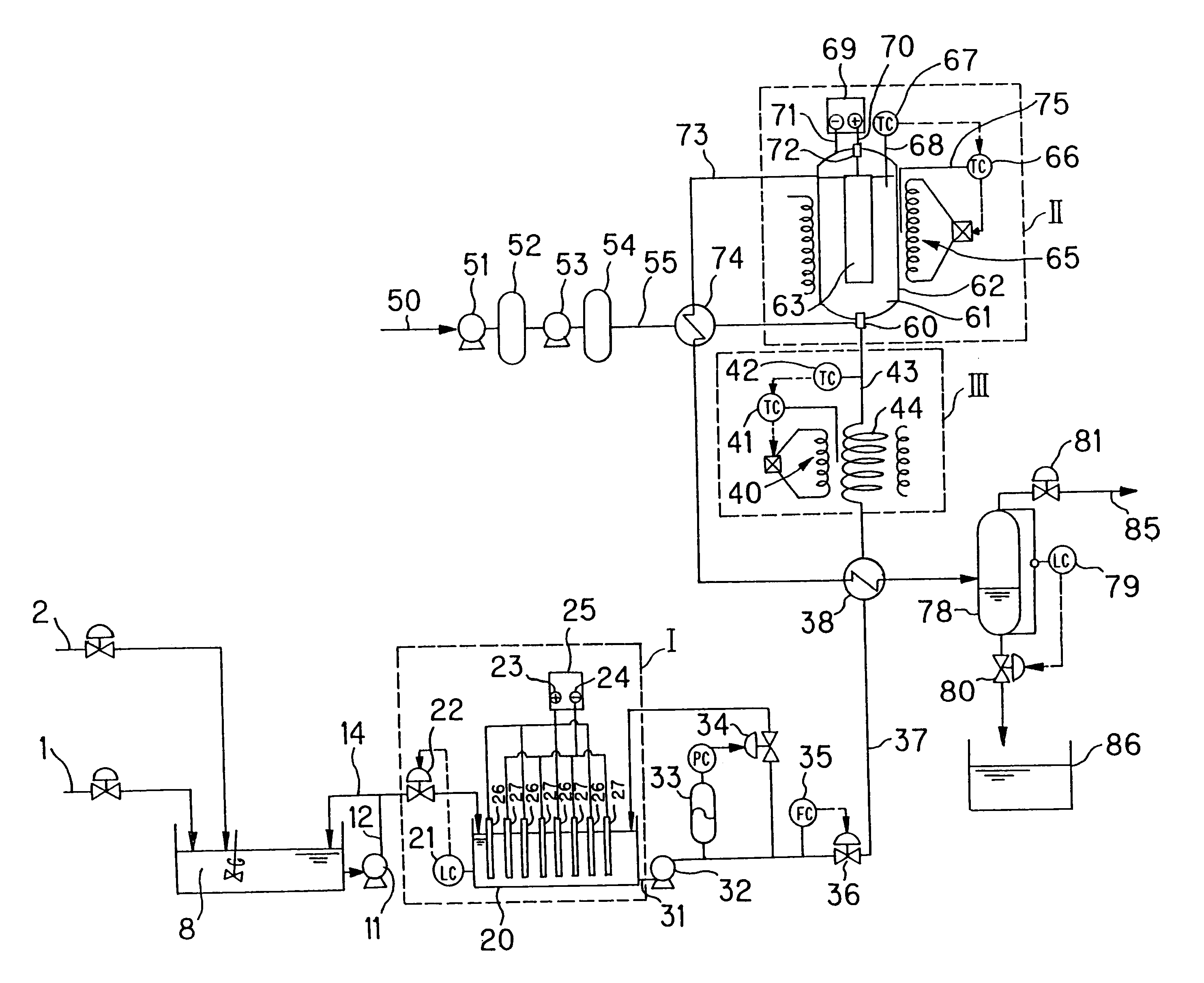
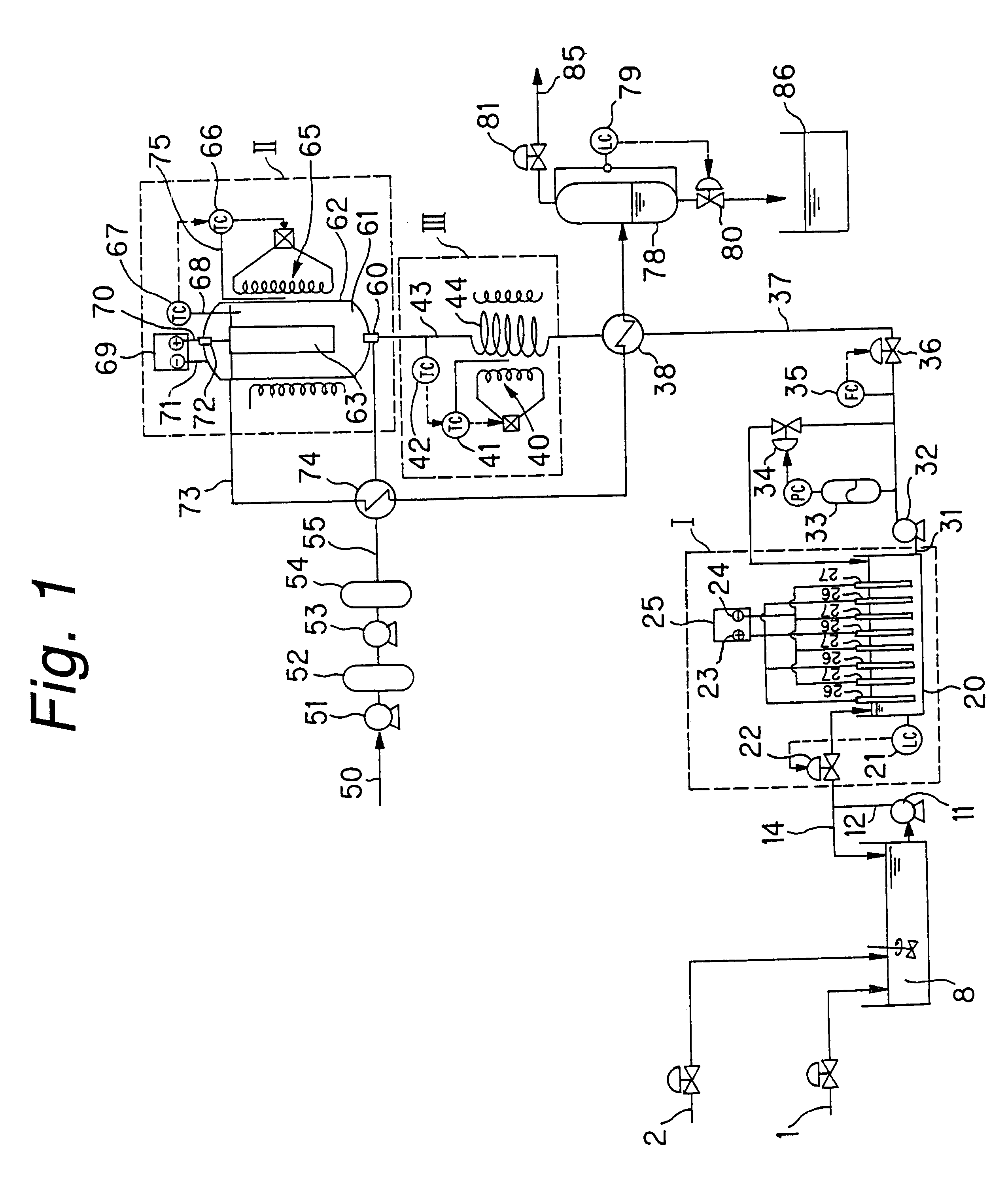
Hydrothermal electrolytic reactor 100 according to the present invention shown in FIGS. 2-4 comprises a lower vessel part, a middle vessel part and an upper vessel part. The lower vessel part comprises an inlet 103 for introducing influent, an oxidizer inlet 104 for introducing an oxidizer, and a mixing chamber 105 for mixing the influent introduced via the inlet and the oxidizer introduced via the oxidizer inlet. The influent and the oxidizer may be mixed in a mixer 60 in the form of a mixing nozzle and then introduced into the reactor, as shown in FIG. 1. The middle vessel part comprises a plurality of reaction cells 101 in which the influent mixed with an oxidizer is electrolyzed under pressure and heating.

The upper vessel part comprises a current feed terminal 106 corresponding to each reaction cell. The current feed terminal preferably has an insulating member 107 for insulating from the reactor. Each current feed terminal has a discharge electrode (anode) 102 extending to the ...

example 1

This example relates to a process according to the first aspect comprising a first step of electrolysis and a second step of hydrothermal electrolysis. Before the hydrothermal electrolysis of Comparative example 1, an electrolytic reaction was performed at normal pressure. In the same autoclave as used in Comparative example 1 shown in FIG. 11 containing sludge having a chloride ion level controlled at 10 mmol / L, an electrolytic current of 6A was applied across ruthenium oxide sintered electrode 406 and the inner face of the container (cathode) for 2 hours while the container was purged with argon via valve 404 opened.

Then, the autoclave was charged with argon in an amount equivalent to 7 MPa, and sealed and heated to a temperature of 250.degree. C. When the temperature reached 250.degree. C., an electrolytic current of 6 A was applied across electrodes for 2 hours. The experimental results are shown in Table 1. Remarkable improvement in TOC and COD in the supernatant was found as c...

example 2

This Example 2 and the following Example 3 relate to a process according to the second aspect of the present invention comprising a first step of hydrothermal reaction and a second step of hydrothermal electrolysis. In Examples 2 and 3, the apparatus shown in FIG. 10 was used. Acetic acid was used a persistent substance, and formic acid was used as a readily degradable substance. Commercially available acetic acid and formic acid were diluted in distilled water each at 4,000 mg / L to prepare an artificial waste liquor. A reagent grade NaCl was further added as a halide ion source at an NaCl concentration of 2 wt % in the waste liquor. TOC of the waste liquor was 2,640 mg / L.

The flow rate of high-pressure pump 94 was set at 100 cc / min (6 L / h), and the flow rate of the compressor for introducing air was set at 5 NL / min (0.3 m.sup.3 / h). A cylindrical iridium sintered electrode 351 was placed in hydrothermal oxidation reactor 350a having an inner volume of 6 L. A cylindrical iridium sint...


PUM

PropertyMeasurementUnit
Angleaaaaaaaaaa
Temperatureaaaaaaaaaa
Pressureaaaaaaaaaa

Abstract

An object of the present invention is to provide a process and an apparatus for treating an aqueous medium at low running costs with a decreased electricity required for hydrothermal electrolytic reaction. The present invention proposes a two-step process comprising a first step of performing a conventional hydrothermal reaction or a conventional electrolytic reaction prior to hydrothermal electrolytic reaction to degrade readily degradable substances or ammonia or various electrolytically degradable organics and then a second step of performing hydrothermal electrolytic reaction to degrade the remaining organics, whereby the electricity consumed by hydrothermal electrolytic reaction in the second step can be greatly reduced.

Description

The present invention relates to aqueous medium treatment processes and apparatus, which can be used to treat organic wastewater, synthesize a product or recover a metal by efficiently performing hydrothermal reaction and electrolysis at the same time. As used herein, hydrothermal electrolysis means that hydrothermal reaction and electrolysis are performed at the same time.PRIOR ARTVarious kinds of waste liquors have been conventionally treated by hydrothermal reaction. Hydrothermal reaction means that an aqueous medium such as waste liquor is exposed to a pressure that allows said aqueous medium to be kept in the liquid phase at high temperature below the critical temperature of the aqueous medium, whereby reducing substances such as organics are degraded at high temperature.However, waste liquors could not be treated at sufficient efficiency by conventional hydrothermal reaction processes.Thus, we proposed an efficient waste liquor treatment process by hydrothermal electrolysis (I...

Claims


Application Information

Patent Timeline
IPC IPC(8): B01D53/77B01J19/18B01J19/26B01D53/32B01J3/04B01J10/00B01J19/00C02F1/461C02F1/467C02F1/02C02F1/74
CPCB01D53/32B01J3/04B01J10/00B01J19/18B01J19/26C02F1/461C02F1/46104C02F1/467C02F1/4672B01D53/77C02F2301/08B01J2219/00054B01J2219/00058B01J2219/00063B01J2219/00069B01J2219/00087B01J2219/00099B01J2219/00103B01J2219/00132B01J2219/00135B01J2219/00155B01J2219/00157B01J2219/00159B01J2219/00162B01J2219/00164B01J2219/00182B01J2219/083B01J2219/0884B01J2219/185B01J2219/30207B01J2219/30223C02F1/02C02F1/025C02F1/46114C02F1/74C02F2001/46133C02F2101/36C02F2103/18C02F2103/28C02F2201/4612C02F2201/46155C02F2301/066
Inventor NISHIMURA, TATSUYASERIKAWA, ROBERTO MASAHIROSU, OINGQUANISAKA, MASAHIROUSUI, TAKASHI
Owner EBARA CORP
Learn More