Lock detector for phase locked loops

a phase lock and detector technology, applied in the direction of pulse automatic control, amplitude demodulation, digital transmission, etc., can solve the problems of phase error response characteristics, high-speed communication system use, and difficult to conceive of a modern high-speed digital communication system, so as to improve system performance

Inactive Publication Date: 2003-06-17
AVAGO TECH INT SALES PTE LTD
View PDF10 Cites 55 Cited by
  • Summary
  • Abstract
  • Description
  • Claims
  • Application Information

AI Technical Summary

Benefits of technology

In an additional aspect of the invention, a low pass filter is coupled between the lock detector and the phase detector circuit. The low pass filter averages phase error component values to remove extraneous high frequency noise and improve system performance. The output of the low pass filter is

Problems solved by technology

Indeed, it is difficult to conceive of a modern high-speed digital communications system that does not make extensive use of precision PLLs.
Notwithstanding the necessity of their use in modern communication systems, conventional PLLs suffer from a particular disadvantage that makes their use in modern, high-speed communication systems problematic.
This disadvantage relates most particularly to the time characteristics of the phase error response of a first order o

Method used


Image

  • Lock detector for phase locked loops
  • Lock detector for phase locked loops
  • Lock detector for phase locked loops

Examples


Embodiment Construction

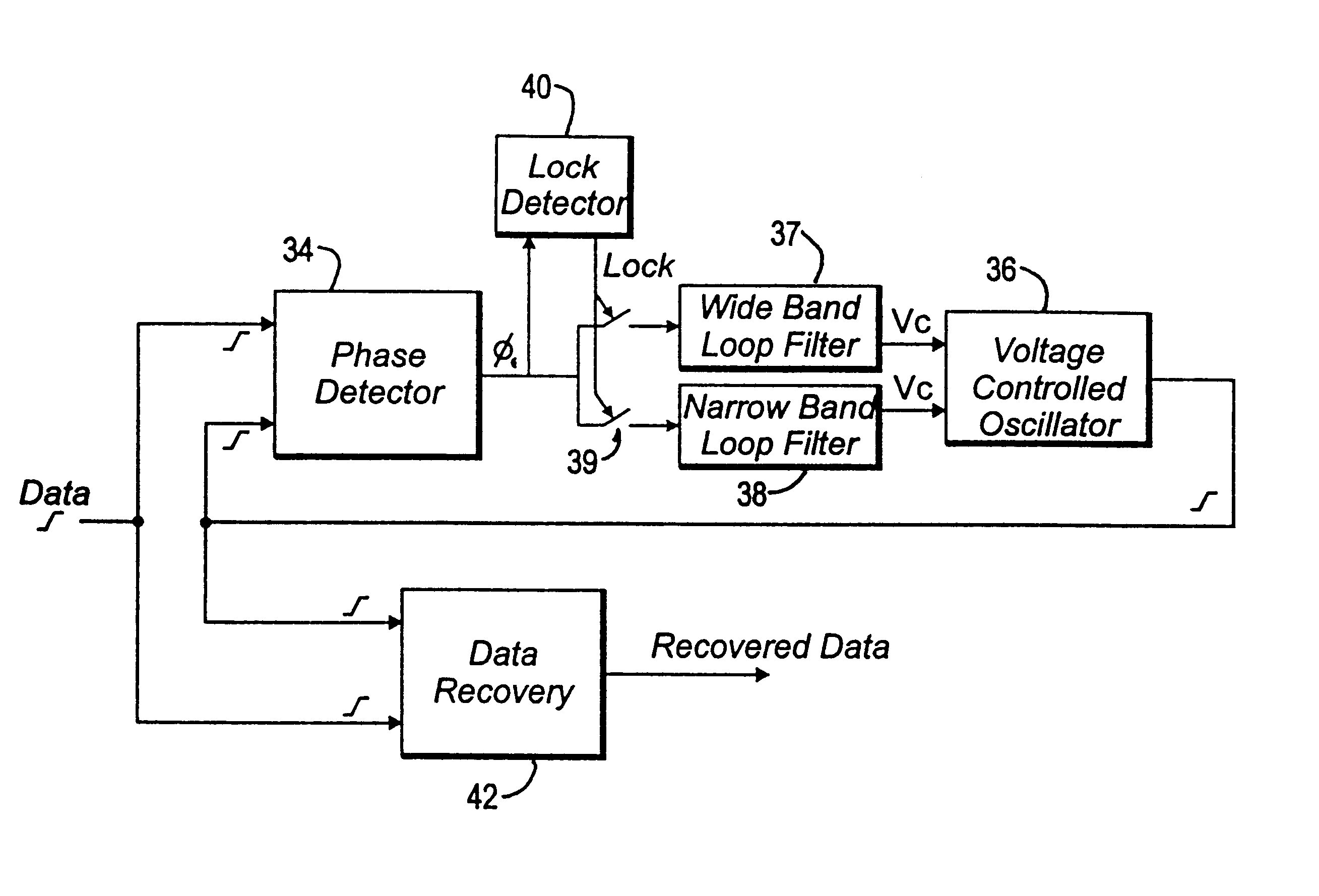
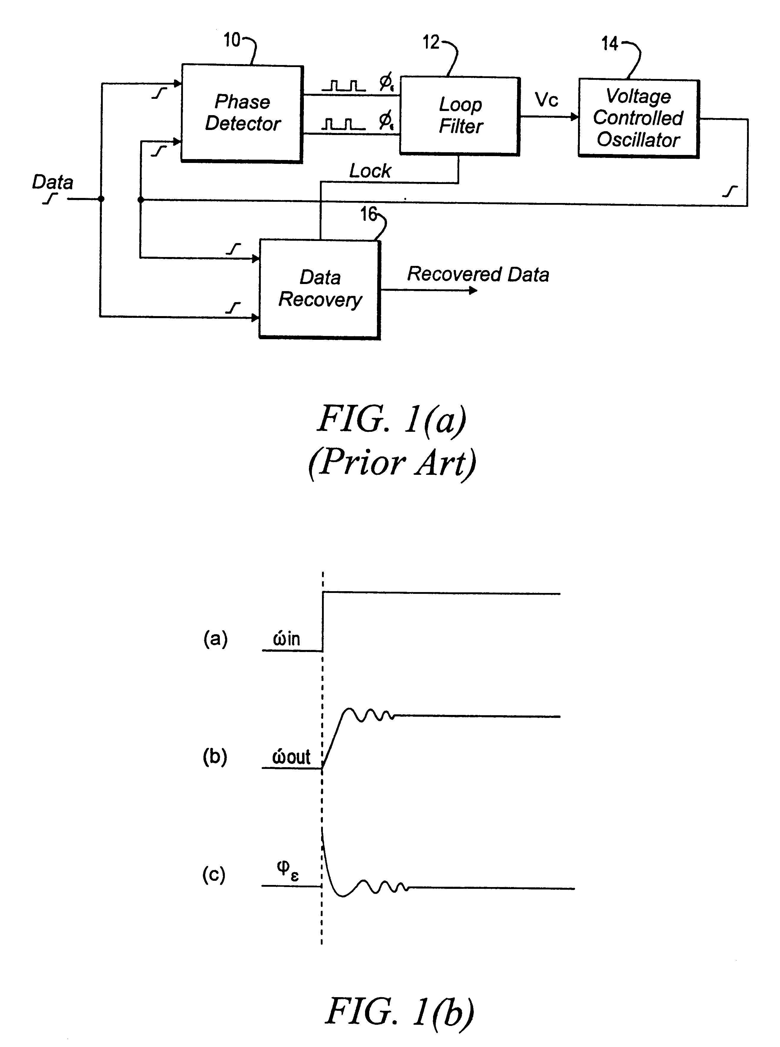
Conceptually, a conventional phase lock loop (PLL), such as depicted in semi-schematic block diagram form in FIG. 1(a), is a feedback system that operates on the excess phase of nominally periodic signals. Implementation of such a PLL normally comprises a phase detector (PD) or phase and frequency detector (PFD) 10 whose output is coupled to a loop filter (low-pass filter or LPF) 12 which, in turn, drives some means for generating a synchronous clock signal 14, such as a voltage controlled oscillator (VCO), current controlled oscillator (CCO) or decision controlled oscillator (DCO). When receiving data, during what is conventionally termed frequency or velocity lock, the oscillation frequency of the clock signal generator (termed a VCO for convenience) is determined by, and locked to the frequency of an external periodic signal source provided for such purpose (not shown), just prior to receiving an input datastream. Once frequency or velocity lock is established, the VCO runs in wh...


PUM


Abstract

A detector circuit for determining whether synchronization lock has been optimally achieved in feedback-type control systems. The detector circuit evaluates an error signal developed by a phase/frequency detector and compares the absolute magnitude of the error signal to a first threshold signal corresponding to a magnitude metric. When the value of the error signal is less than the magnitude threshold value, an event signal initiates a time interval counter which continues counting so long as the error signal remains below the magnitude threshold value. The time interval counter continues until it counts to a second threshold value corresponding to a timing metric. At this point, synchronization lock is declared.

Description

FIELD OF THE INVENTIONThe present invention relates generally to lock detectors for phase lock loops and, more particularly, to a lock detector which establishes upper and lower bounds to a lock range in order to ensure that phase error is substantially confined within the range before acquisition of lock is declared.BACKGROUND OF THE INVENTIONPhase lock loops (PLLs) and clock recovery circuits (CRCs) have found wide application in such diverse areas as digital communication systems, wireless systems, digital circuits and data recovery systems for use in connection with mass storage media such as hard disk, tape and optical drives. In the field of digital communication systems, phase lock loops are typically used in modern digital communications receivers to recover useful data from a transmission signal stream by providing data recovery circuitry with a timing reference having the appropriate frequency and phase characteristics so as to match timing characteristics of the transmitt...

Claims


Application Information

Patent Timeline
IPC IPC(8): H03L7/08H03L7/095H03L7/107
CPCH03L7/095H03L7/107Y10S331/02H03L7/1075
Inventor TAN, LOKE KUNETEMADI, FARZADYUEN, DENNYTSAI, SHAUHYARN SEAN
Owner AVAGO TECH INT SALES PTE LTD
Why Eureka
Try Eureka