
Recording unit and image recording apparatus

a recording unit and image technology, applied in the direction of measuring apparatus components, instruments, inks, etc., can solve the problems of deterioration of discharge performance, bleeding of color image quality, visual abnormal image,

Inactive Publication Date: 2003-06-24
CANON KK
View PDF22 Cites 35 Cited by
  • Summary
  • Abstract
  • Description
  • Claims
  • Application Information

AI Technical Summary

Benefits of technology

Another object of the present invention is to provide the recording unit and the image recording apparatus capable of improving discharge durability while keeping the above-described feature of using a black ink and a color ink containing a polyvalent metal salt reactive to the black ink.
A still further object of the present invention is to provide a recording unit and an image recording apparatus capable of showing effectively an effect of eliminating a difference in density of an image between a part recorded by a blend of the black ink and the color ink reactive to the black ink as described above and a part recorded by using the black ink alone also in high speed printing by improving shooting precision in high speed printing.
According to the present invention, for example, by adopting combination of a black ink and a color ink containing a polyvalent metal salt reactive to the black ink, it is realized effects that none of bleeding and white haze occurs in a boundary region between the black ink and other color ink and that a black image formed by overlaying the color ink on the black ink for prevention of bleeding can be formed in a very high density almost the same as that of a black image formed by using the black ink alone to yield a high quality image presenting visually evenness. Further, the cavitation resistant film formed by at least two layers, of which an upper layer contacting with the ink is a Ta film or a TaAl film and a lower layer is a layer of an amorphous alloy containing Ta, is used at a part contacting with the ink on at least the heat-generating resistor member in the liquid flow path of the ink jet head, whereby discharge durability can be further improved keeping such effects.
In addition, also in case of applying the black ink and the color ink by overlaying to express a monotonous gradation, the following problem takes place: the conventional art causes the difference in optical density by the same reason described above and therefore, in order to make a smooth tone expression, a composition ratio of the black ink and the color ink is limited to cause decrease in a degree of freedom and deterioration of the smooth tone expression itself. However, applying the present invention allows making almost the same as the optical density of the part in which the black ink agglomerates and the optical density of the part formed by only the black ink and therefore, by adjusting a proportion of the color ink added to the black ink, a desired tone expression can be realized and also other effect that the image of a more excellent multigradation expression can be realized is yielded.

Problems solved by technology

On the other hand, the ink jet recording method has a problem that when different two kinds of inks are applied to the recording medium, the inks are mixed with each other on a boundary part between them to cause a phenomenon (bleeding) of lowering a quality of a color image.
However, when a part formed with a black ink and a part formed by a blend of a color ink and the black ink coexist in a black area in the same document, the image density of black may differ from each other to result in a visually abnormal image.
In other words, in case of using the ink containing a polyvalent metal salt, the part contacting with the ink may corrode during use for a long term to disorder discharge stability and cause deterioration of discharge performance in some occasions corresponding to a material quality thereof.
In addition, also in case of applying the black ink and the color ink by overlaying to express a monotonous gradation, the following problem takes place: the conventional art causes the difference in optical density by the same reason described above and therefore, in order to make a smooth tone expression, a composition ratio of the black ink and the color ink is limited to cause decrease in a degree of freedom and deterioration of the smooth tone expression itself.
Unstabilization of the dispersion stability of the coloring material in the black ink in such ink combination is, specifically, agglomeration of the coloring material, precipitation, or thickening of the black ink, and the like.
In this example, when the color ink is blended with the black ink, the polyvalent metal cation of the polyvalent metal salt reacts to the anionic group of the coloring material in the black ink and as the result, the coloring material in the black ink causes dispersion break, agglomeration of the coloring material, and thickening of the ink.
In other words, slow solid-liquid separation when the ink is applied to the recording medium disperses the ink having a large Ka value or the ink on the paper showing large ink penetrability in the paper isotropically together with the coloring material and as the result, sharpness of a character (quality of the character) is damaged and also the coloring material penetrates into a back of the paper presumably to decrease optical density.
In addition, remaining ratio of reflection strength of individual colors is large; total light fading of the image can be difficulty recognized.
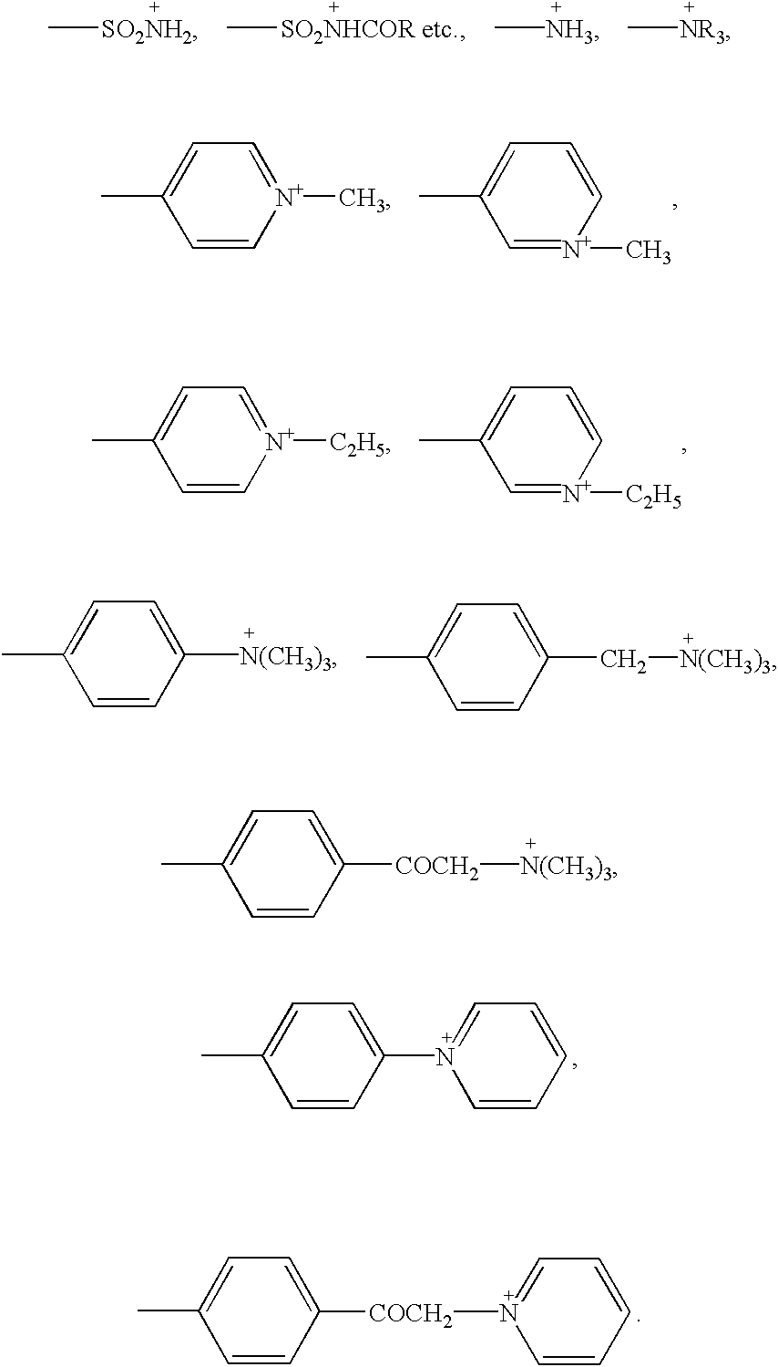
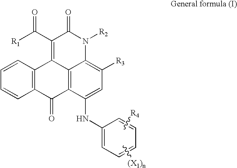
When the weight ratio of the compound of the general formula (I) becomes further larger, some recording medium does not occasionally provide clear tone and image density and also when the weight ratio becomes further smaller, enough light resistance may not be yielded.

Method used


Image

  • Recording unit and image recording apparatus
  • Recording unit and image recording apparatus
  • Recording unit and image recording apparatus

Examples


Embodiment Construction

Described below specifically with reference to examples and comparative examples, the present invention is not restricted to the following examples and various modifications can be allowed in a range within the scope thereof. For reference, unless defined specially, "part" and "%" in the following description means will be expressed on mass standard.

First of all, a pigment dispersion 1 was prepared.

Pigment dispersion 1

10 g of carbon black, of which specific surface area was 230 m.sup.2 / g and DBP oil absorption was 70 mL / 100 g, and 3.41 g of p-amino-N-benzoic acid were enough mixed with 72 g of water and then, 1.62 g of nitric acid was dropped to stir at 70.degree. C. In addition, after several minutes, a solution prepared by dissolving 1.07 g of sodium nitride in 5 g of water was added to stir further for 1 hour. Slurry yielded was filtered through a filter paper (commercial name: Toyo Filter Paper No. 2; made by Advantis Co.), a pigment particle filtered was washed enough with wat...


PUM

PropertyMeasurementUnit
carbon numberaaaaaaaaaa

Abstract

A recording unit is provided which includes an ink housing part for housing an ink containing a coloring material and an aqueous medium, and an ink jet head part for discharging an ink droplet of the ink, wherein at least one color of the ink is a polyvalent metal salt containing ink further containing a polyvalent metal salt; the ink jet head part for discharging at least the polyvalent metal salt containing ink has a configuration comprised of a substrate having on a base body, a heat-generating resistor member forming a heat-generating part, an electrode wire electrically connected to the heat-generating resistor member, and a cavitation resistant film provided on the heat-generating resistor member and the electrode wire via an insulating protection layer, and a liquid flow path communicating with a discharge port for discharging an ink droplet provided corresponding to the heat-generating part; and the cavitation resistant film includes a layer comprised of an amorphous alloy containing Ta and a layer comprised of an amorphous body of an amorphous alloy which is rich in Ta than the amorphous alloy containing Ta or a passive matter of the amorphous body provided on the layer comprised of the amorphous alloy containing Ta.

Description

1. Field of the InventionThe present invention relates to a recording unit and an image recording apparatus.2. Related Background ArtThe ink jet recording method is a low-noise and non-impact recording method to record an image by discharging an ink directly on a recording medium. Further, this method does not require a complicated apparatus in operation and hence, a low running cost, miniaturization of the apparatus, and color printing are easy to realizeTherefore, recording apparatuses such as a printer, a copier, a facsimile, a word processor, and the like, to which the ink jet recording method is applied, have been so far put into practical use. By applying such ink jet recording technology, color ink jet recording apparatuses to form a multicolor image using a black ink and a color ink (for example, at least one color ink chosen from a yellow ink, a cyan ink, a magenta ink, a red ink, a green ink, and a blue ink) have also been put into practical use.On the other hand, the ink ...

Claims


Application Information

Patent Timeline
Patent Type & Authority Patents(United States)
IPC IPC(8): B41J2/14B41J2/21C09D11/00
CPCB41J2/14048C09D11/40B41J2/2107B41J2202/03
Inventor TAKADA, YOICHIOZAKI, TERUOMATSUMOTO, NOBUYUKIKATO, MASAO
Owner CANON KK
Learn More