Method and device for referencing fluorescence intensity signals

Inactive Publication Date: 2003-08-05
ROCHE DIAGNOSTICS GMBH +1
View PDF19 Cites 92 Cited by
  • Summary
  • Abstract
  • Description
  • Claims
  • Application Information

AI Technical Summary

Problems solved by technology

This will also apply to undefined optical properties of the sample (such as turbidity, intrinsic colour, or refractive index), which could cause problems in intensity measurements.
As a consequence, both decay time and luminescence quantum efficiency will decrease.
A precondition for this method is that both forms of an indicator are luminescent, and that their absorption and emission spectra show significant overlap.
Accurate measurements of decay times in the lower nanosecond region necessitate expensive instrumentation, however, as they require not only very fast circuitry and high modulation frequencies but also fast light sources and detectors.
One serious problem with the practical use o

Method used


Image

  • Method and device for referencing fluorescence intensity signals
  • Method and device for referencing fluorescence intensity signals
  • Method and device for referencing fluorescence intensity signals

Examples


Embodiment Construction

by means of examples.

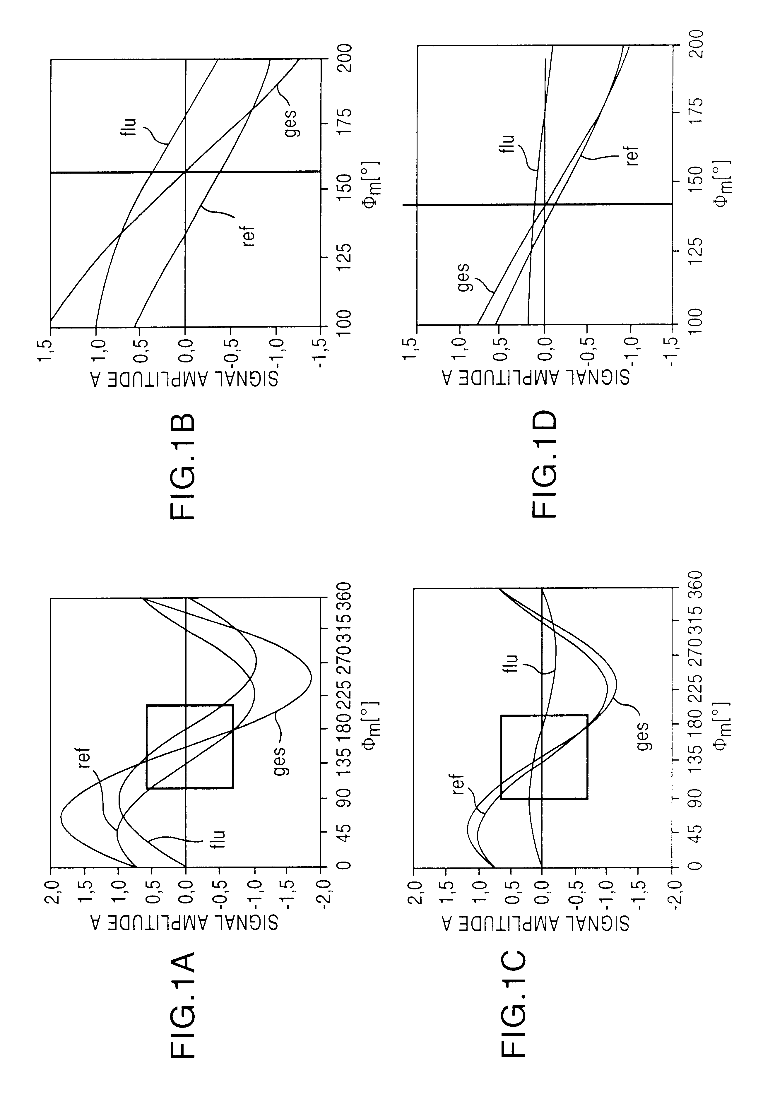
FIG. 1 shows the dependence of the measured phase angle .phi..sub.m on the relationship between intensity of the fluorescence indicator and the reference luminescent material; A strong fluorescence signal, B weak fluorescence signal. Labels used are flu=variable fluorescence signal, ref=constant reference signal, ges=measured total signal;

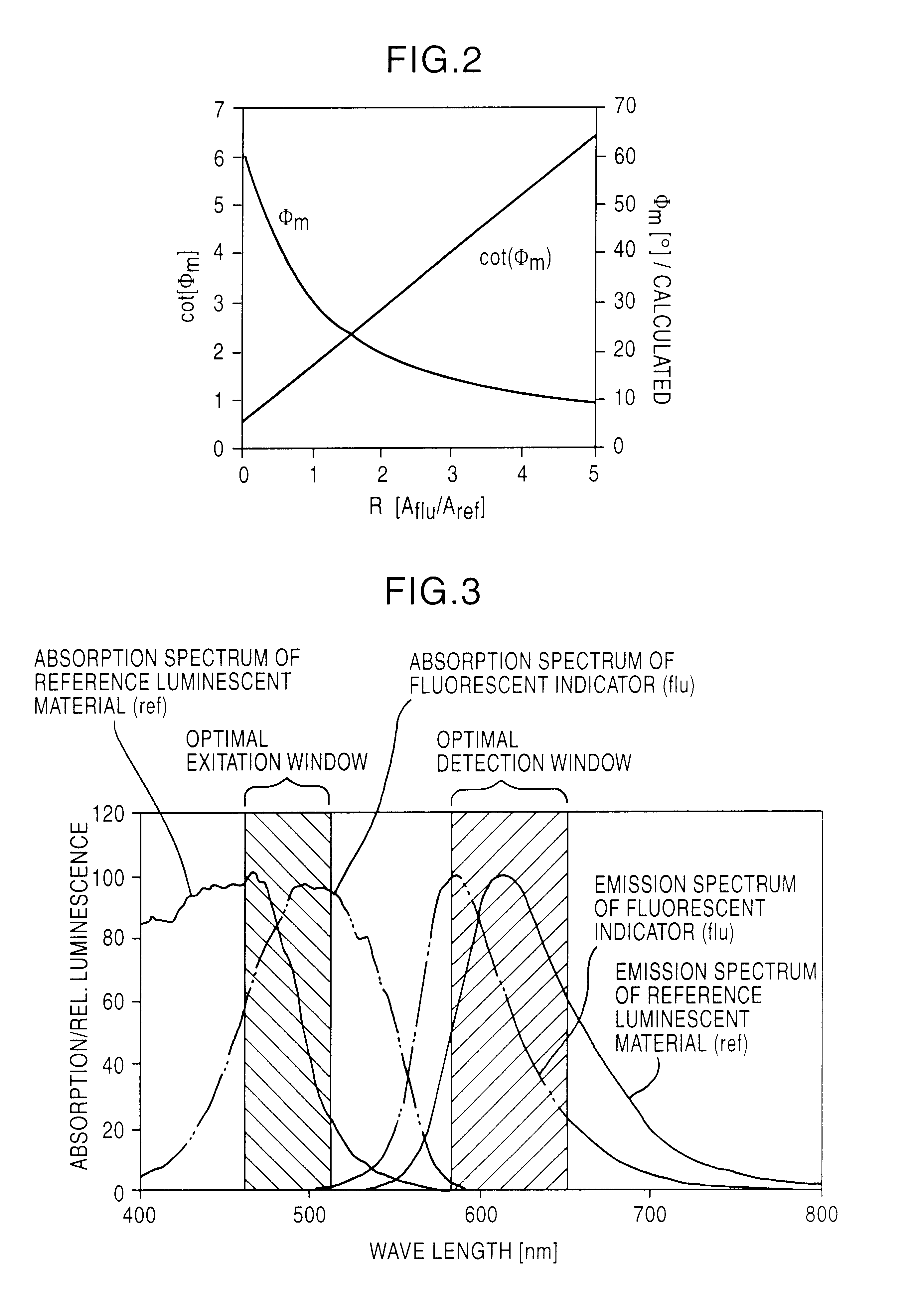
FIG. 2 shows a computed relationship between the measured phase angle .phi..sub.m or its cot (.phi..sub.m) and the amplitude ratio R of the two luminescent materials;

FIG. 3 shows spectral properties of a suitable pair of fluorescence indicator and reference luminescent material. The hatched areas indicate optimum spectral windows for excitation of the luminescence signal and measurement of the emitted light;

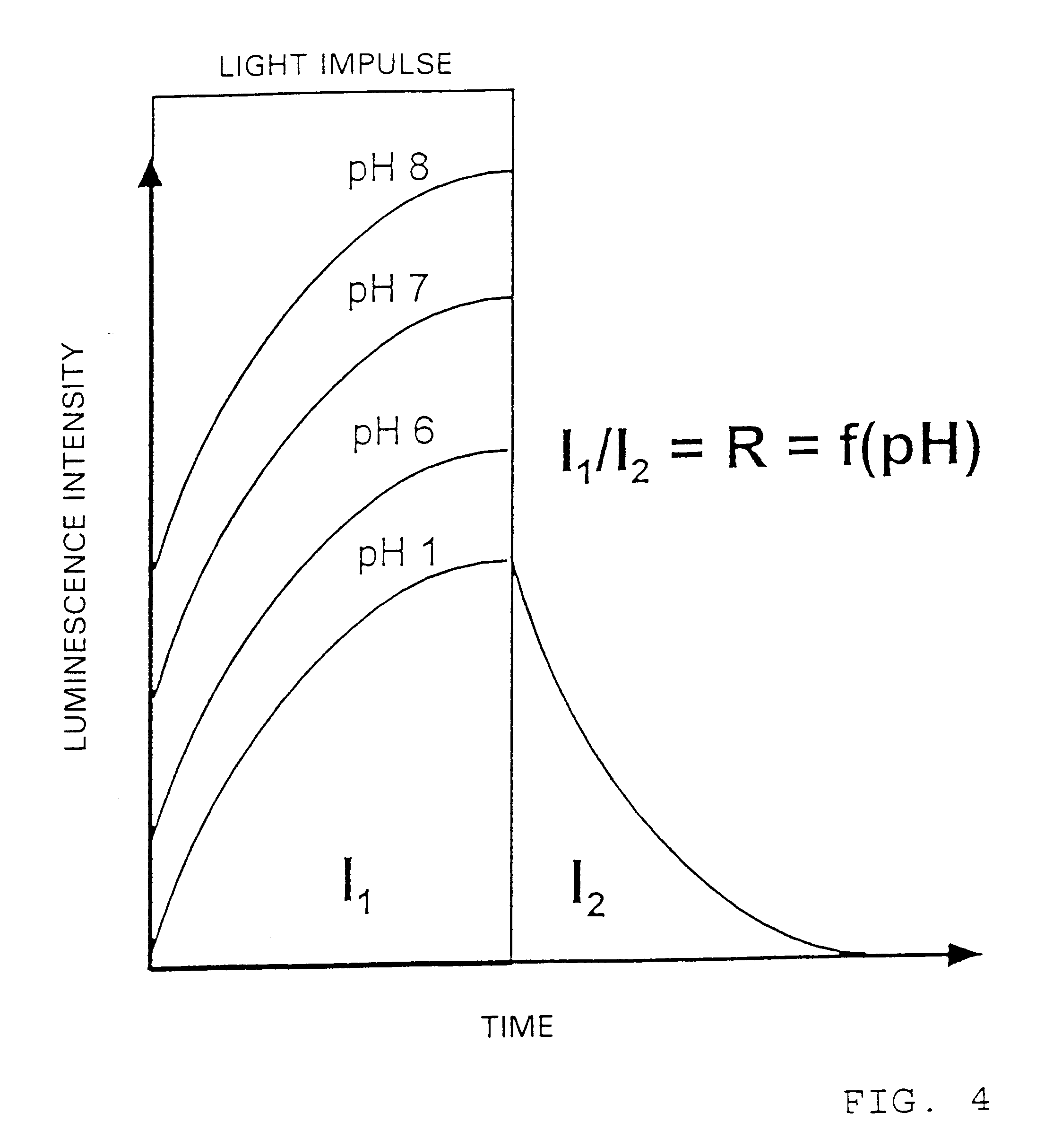
FIG. 4 shows a time-resolved measurement of the ratio of signal intensities during the excitation pulse (I.sub.1) and during luminescence decay (I.sub.2), the ratio R being independent of the total signal amplitude, as it is...


PUM

PropertyMeasurementUnit
Timeaaaaaaaaaa
Concentrationaaaaaaaaaa
Decay rateaaaaaaaaaa

Abstract

A method and device for fluorimetric determination of a biological, chemical or physical parameter of a sample utilize at least two different luminescent materials, the first of which is sensitive to the parameter, at least with respect to luminescence intensity, and the second of which is insensitive to the parameter, at least with respect to luminescence intensity and decay time. The luminescent materials have different decay times. The time- or phase behaviour of the resulting luminescence response is used to form a reference value for determination of a parameter.

Description

(1) Field of the InventionThe invention relates to a method and device for use with a spectrophotometer, for fluorimetric determination of a biological, chemical or physical parameter of a sample, utilizing at least two different luminescent materials, the first of which is sensitive to the parameter at least with respect to luminescence intensity, and the second of which is insensitive to the parameter at least with respect to luminescence intensity and decay time.The invention relates in particular to a new principle of optical detection of chemical parameters with the use of optical sensors, based on phase shift- and time-resolved measurements. The modulation frequencies used are between 0.5 and 5 MHz and may be detected with the use of low-cost optical semiconductor components.(2) Description of the Related ArtAs is known from the literature and practical experience with optical sensors, determining decay time instead of intensity as a measurement variable has certain practical ...

Claims


Application Information

Patent Timeline
IPC IPC(8): G01N21/64G01N15/14G01N21/76
CPCG01N21/6428G01N2021/6417Y10S435/808Y10T436/10Y10S435/973Y10S436/805Y10S436/823Y10S436/80
Inventor KLIMANT, INGO
Owner ROCHE DIAGNOSTICS GMBH
Why Eureka
Try Eureka