Protection for a carbon material, in particular C/C composite, bowl that is to receive a crucible, such as a silica crucible for drawing silicon

a technology of carbon materials and protective fluids, applied in the direction of protective fluids, lighting and heating devices, furniture, etc., can solve the problems of limited contact area and achieve the effects of reducing the extent, reducing the cost, and limiting the mechanical stress

Inactive Publication Date: 2003-09-09
SNECMA MOTEURS SA
View PDF8 Cites 4 Cited by
  • Summary
  • Abstract
  • Description
  • Claims
  • Application Information

AI Technical Summary

Benefits of technology

An object of the invention is to propose a solution to the above-specified problems that is simple and of low cost, making it possible to reduce considerably the extent to which the crucible material corrodes bowls made of carbon material, in particular C / C composite material, and making it possible to limit the mechanical stresses that are generated in bowls, thereby lengthening the service lifetime of bowls.
The invention is remarkable in that in spite of its small thickness and its porosity, such a buffer ply provides protection which is effective, as described in greater detail below. In addition, such a ply, even though it needs to be replaced periodically, and as a result constitutes a consumable, nevertheless provides protection at relatively low cost.
In addition, such a buffer ply, because it has the ability to deform in its thickness and because it is not bonded to the material of the bowl, limits the extent to which stresses are generated in the bowl as a result of differential variations in dimensions between the bowl and the crucible, and makes it easier to withdraw the crucible at the end of a crystal-drawing cycle.
According to a feature of the method, prior to putting the buffer ply into place in the bowl, a thin coating of pyrolytic carbon can be formed on the fibers of the ply. Such a thin coating can be formed so as to "fix" the fibers and prevent them from becoming separated while the bowl is in use. The thin coating of pyrolytic carbon could also be made on the buffer ply while it is held in a desired shape, so as to "preform" the buffer ply into a shape that is at least close to the desired shape, while not causing the ply to become rigid.
In practice, the thickness of the coating of pyrolytic carbon on the fibers should not exceed 4 microns (.mu.m), and is preferably no greater than 2 .mu.m. The thin coating of pyrolytic carbon can also avoid impurities diffusing from the fibers to the crucible.

Problems solved by technology

Such a fabric also has macropores and offers limited contact area with the solid surface against which it is applied.

Method used


Image

  • Protection for a carbon material, in particular C/C composite, bowl that is to receive a crucible, such as a silica crucible for drawing silicon
  • Protection for a carbon material, in particular C/C composite, bowl that is to receive a crucible, such as a silica crucible for drawing silicon
  • Protection for a carbon material, in particular C/C composite, bowl that is to receive a crucible, such as a silica crucible for drawing silicon

Examples


example 1

A fiber fabric was made by knitting a commercially available 6K carbon yarn, i.e. a yarn made up of 6000 carbon filaments;

A lose interlock structure knit was used with the weight per unit area of the knit being about 300 grams per square meter (g / m.sup.2), and with the thickness of the knit being approximately equal to 1.5 mm.

The fabric was cut out to provide a disk having a diameter of 700 mm and carbon thread edging was used to prevent the fabric from fraying.

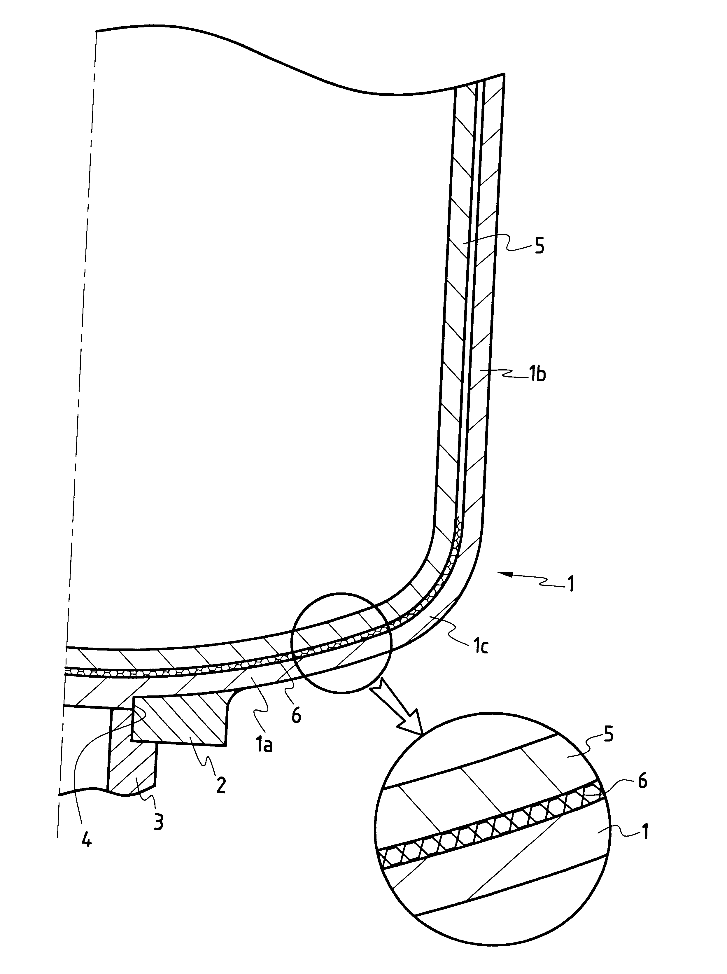
The resulting ply was placed on the bottom of a C / C composite bowl having a diameter of 22 inches (about 460 mm) so as to line the bottom of the bowl and the adjacent zone of the connecting portion prior to putting a silicon-containing crucible into place.

After a silicon crystal-drawing cycle, the crucible and the buffer ply were removed from the bowl, sometimes in pieces, and discarded. Because the buffer ply had been used, the bottom of the bowl presented very few traces of chemical attack (consumption of the bowl wall) or ...

example 2

A fiber fabric was made by weaving (plain weave) commercially available 1K carbon yarns. The resulting cloth was inserted into a chemical vapor infiltration oven to form a thin deposit of pyrolytic carbon on the fibers, the deposit having a thickness of about 0.5 .mu.m. A conventional gas was used containing methane as the carbon precursor.

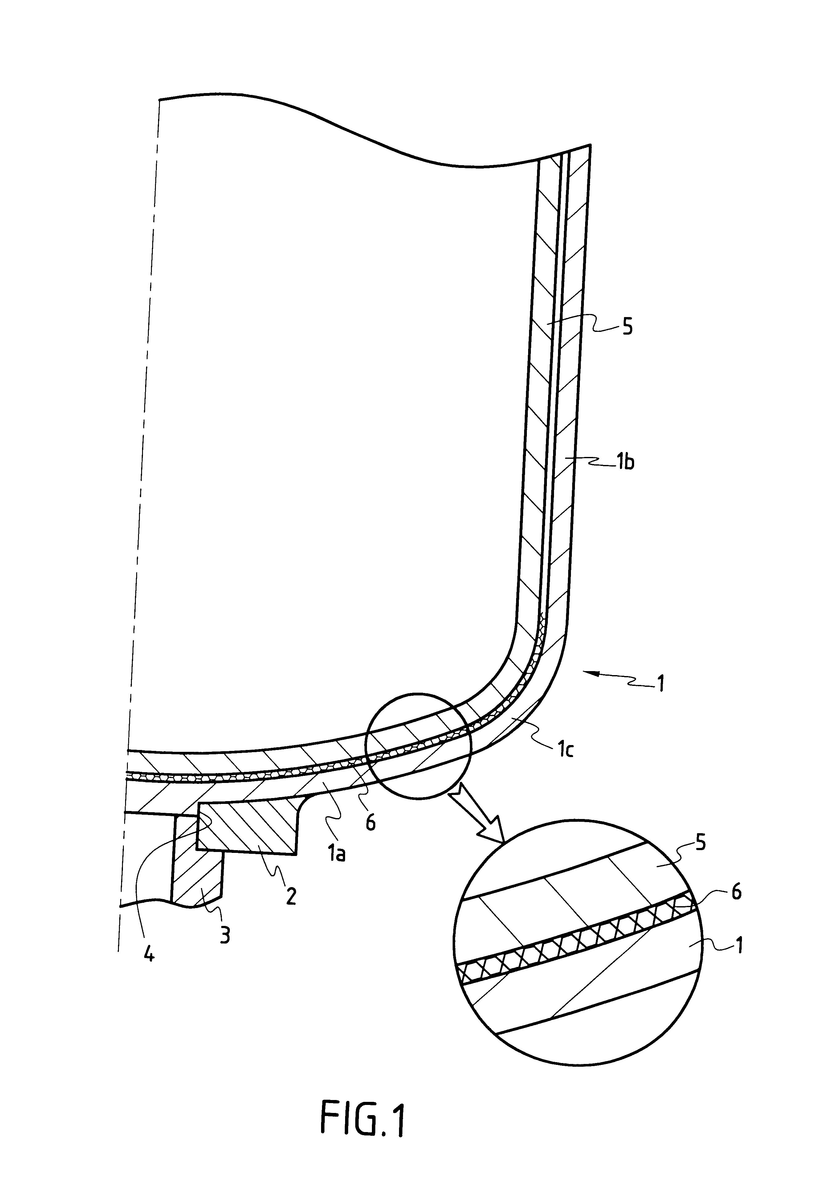
The resulting cloth remained flexible and was cut using a water jet so as to obtain a shape similar to that shown in FIG. 2.

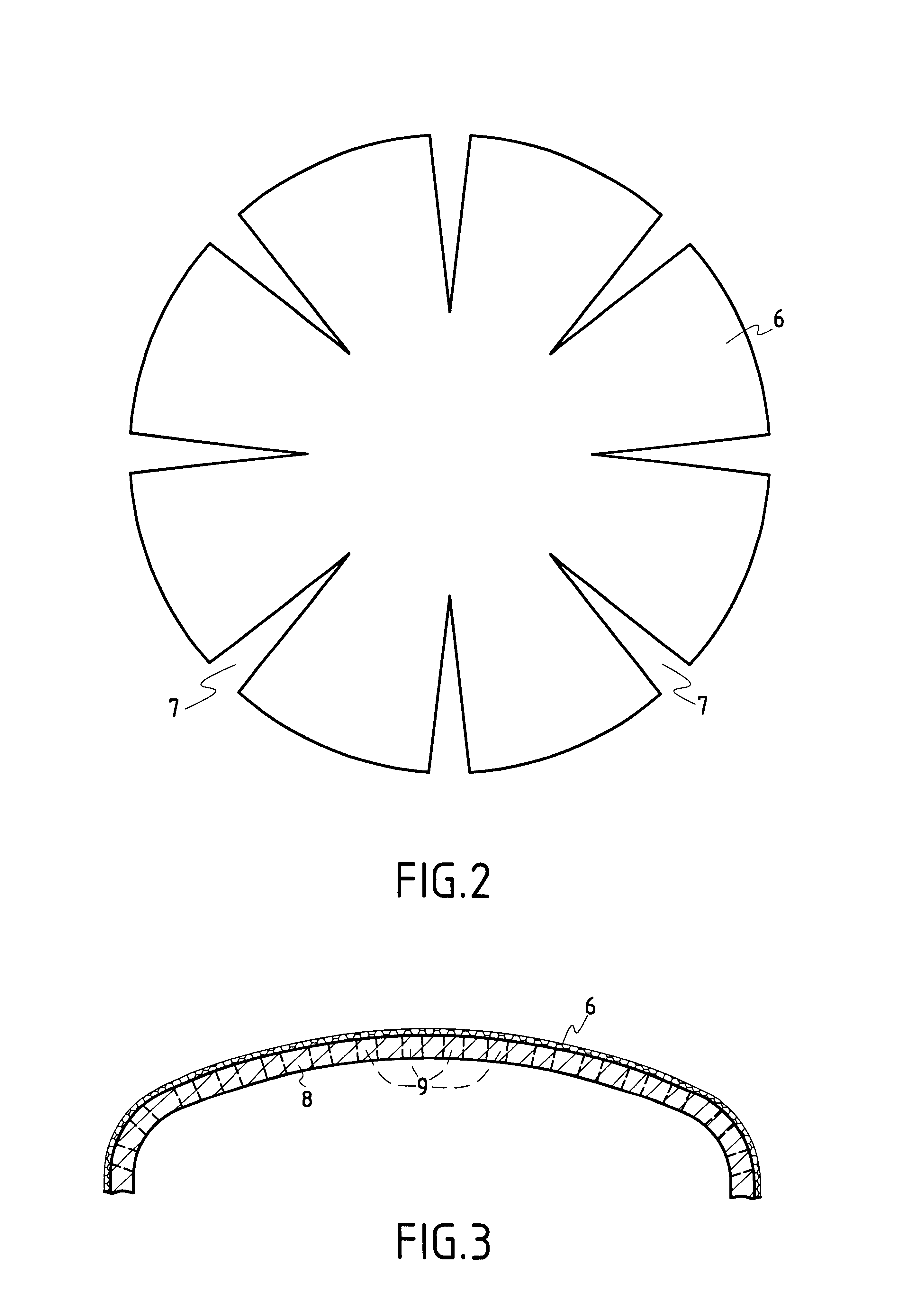
The shapable buffer ply that resulted therefrom was placed between the bottom of a bowl made of C / C composite material and a crucible.

After a silicon crystal-drawing cycle, and after the crucible and the residue of the buffer ply had been withdrawn, it could be seen that the bottom of the bowl presented very few traces of chemical attack or of mechanical stress.


PUM

PropertyMeasurementUnit
thicknessaaaaaaaaaa
thicknessaaaaaaaaaa
thicknessaaaaaaaaaa

Abstract

Prior to housing the crucible in the bowl, a consumable buffer ply is applied over at least a portion of the inside face of the bowl, the ply being constituted essentially by a non-rigid carbon fiber fabric for protecting the bowl from both physical and chemical interactions with the crucible. The buffer ply is essentially constituted by a flexible fabric selected from: a woven cloth, a knit, a multidirectional sheet, and a thin felt. Prior to putting the ply into place in the bowl, it is possible to form a thin deposit of pyrolytic carbon on the fibers of the fabric.

Description

The invention relates to bowls of carbon material, in particular of carbon / carbon (C / C) composite material, used for receiving a crucible in a metallurgical installation.A particular field of application of the invention is that of bowls for receiving crucibles for drawing silicon single crystals.A well-known process of producing a silicon single crystal, in particular for the purpose of fabricating semiconductors, consists in melting silicon in a receptacle, in putting the bath of liquid silicon into contact with a seed crystal having the desired crystal configuration, thereby initiating solidification of the silicon with this crystal configuration, and in mechanically drawing the resulting single crystal out from the crucible. That process is known as the Czochralski process or the "Cz" process.The receptacle containing the molten silicon is frequently a crucible made of silica or of quartz (SiO.sub.2) placed in a bowl, which bowl is sometimes referred to as a "susceptor". Heating...

Claims


Application Information

Patent Timeline
Patent Type & Authority Patents(United States)
IPC IPC(8): C30B15/10F27D1/00C30B29/06F27B14/10
CPCC30B15/10F27D1/00Y10T117/10Y10T117/1052F27D1/0023
Inventor THEBAULT, JACQUESGEORGES, JEAN MICHELCOUPE, DOMINIQUE
Owner SNECMA MOTEURS SA
Why Eureka
Try Eureka