Material and method for making an electroconductive pattern

a technology of electroconductive patterns and materials, applied in the field of materials and methods for making electroconductive patterns, can solve the problems of high fabrication cost, limited application range, low flexibility (pliability) and stretchability, etc., and achieve the effect of simple and convenient method

Inactive Publication Date: 2003-09-23
AGFA GEVAERT AG
View PDF10 Cites 14 Cited by
  • Summary
  • Abstract
  • Description
  • Claims
  • Application Information

AI Technical Summary

Benefits of technology

It is an aspect of the present invention to provide a material having an outermost layer that can be processed to an electroconductive pattern by a simple, convenient method.
A light-exposure differentiable element, according to the present invention, is an element which upon light exposure produces changes in the properties or composition of the exposed parts of the element with respect to the properties or composition of the unexposed parts of the element. According to the present invention, these changes in the properties or composition of the light-exposure differentiable element are due to the presence of a monodiazonium salt in the outermost layer and / or optional contiguous second layer, which upon exposure increases the surface resistance of the exposed areas. The optional second layer must be between the outermost layer and the support as it cannot be the outermost layer. Combinations of monodiazonium salt can also be used. Increasing the pH of the coating dispersions and solutions used in preparing the light-exposure differentiable element has been found to improve the shelf-life of materials according to the present invention. pH's between 2.5 and 9 are preferred, with pH's between 3 and 6 being particularly preferred. Such pH's can, for example, be advantageously realized by adding ammonium hydroxide.

Problems solved by technology

The range of potential applications is limited, because of the high fabrication costs, the low flexibility (pliability) and stretchability as a consequence of the brittleness of the ITO layer and the glass substrate.
Such methods are cumbersome as they involve many steps and require the use of hazardous chemicals.

Method used


Image

  • Material and method for making an electroconductive pattern
  • Material and method for making an electroconductive pattern
  • Material and method for making an electroconductive pattern

Examples


example 1

EXAMPLE 1 discloses the evaluation of different monoaryldiazonium salts: MADS01 to 04, MADS07 and MADS08 incorporated in the PEDOT / PSS-containing outermost layer. Samples I to VIII were prepared by coating Support nr. 1 with the dispersions given in Table 1 to a wet thickness of 40 .mu.m followed by drying at 50.degree. C. for 5 minutes.

The resulting ingredient coverages with Samples I to VIII are given in Table 2.

The layers of Samples I to VIII were exposed through a mask on a PRINTON.TM. CDL 1502i UV contact exposure unit (from AGFA-GEVAERT N.V.) for 400 s at 4 mW / cm.sup.2 (=exposure of 1.6 J / cm.sup.2) with the samples above the glass filter, rinsed for 4 minutes with deionized water at room temperature and finally dried for 4 minutes at 50.degree. C. No difference was observed in the surface resistances observed whether exposure times of 100 s or 400 s were used as long as subsequent rinsing with water was carried out. Furthermore, the degradation process appeared to continue if ...

example 2

EXAMPLE 2 discloses the evaluation of different monoaryldiazonium salts: MADS05 to 07 incorporated in the PEDOT / PSS-containing outermost layer. Samples IX to XIV were prepared by coating Support nr. 1 with the dispersions given in Table 4 to a wet thickness of 40 .mu.m followed by drying at 50.degree. C. for 5 minutes.

The ingredient coverages of the dried layers of Samples IX to XIV are given in Table 5.

The layers of Samples IX to XIV were exposed through a mask on a PRINTON.TM. CDL 1502i UV contact exposure unit (from AGFA-GEVAERT N.V.) for 400 s at 4 mW / cm.sup.2 (=exposure of 1.6 J / cm.sup.2) with the samples above the glass filter, rinsed for 4 minutes with deionized water at room temperature and finally dried for 4 minutes at 50.degree. C. The surface resistances of the non-exposed and exposed areas of the light-exposure differentiable element before and after rinsing with water are given in Table 6.

All samples containing mono(aryldiazosulphonate) compounds exhibited a differenti...

example 3

EXAMPLE 3 discloses the evaluation of different monoaryldiazonium salts: MADS01 incorporated in the PEDOT / PSS-containing outermost layer in different concentrations. Samples XV to XX were prepared by coating Support nr. 1 with the dispersions given in Table 7 to a wet thickness of 40 .mu.m. The ingredient coverages in Samples XV to XIX after drying at 50.degree. C. for 5 minutes are also given in Table 7.

The layers of Samples XV to XX were exposed through a mask on a PRINTON.TM. CDL 1502i UV contact exposure unit (from AGFA-GEVAERT N.V.) for 400 s at 4 mW / cm.sup.2 (=exposure of 1.6 J / cm.sup.2) with the samples above the glass filter, rinsed for 4 minutes with deionized water at room temperature and finally dried for 4 minutes at 50.degree. C. The surface resistances of the non-exposed and exposed areas of the light-exposure differentiable element before and after rinsing with water are given in Table 8.

The results in Table 8 show that the differentiation in surface resistance (R.sub...


PUM

PropertyMeasurementUnit
temperaturesaaaaaaaaaa
temperatureaaaaaaaaaa

Abstract

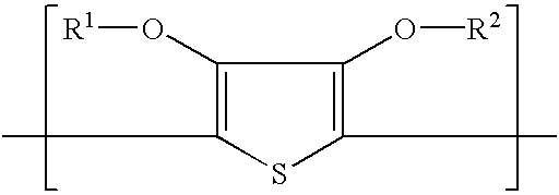
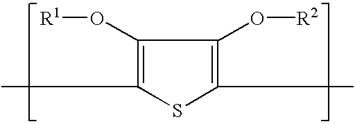
A material for making an electroconductive pattern, the material comprising a support and a light-exposure differentiable element, characterized in that the light-exposure differentiable element comprises a conductivity enhanced outermost layer containing a polyanion and a polymer or copolymer of a substituted or unsubstituted thiophene, and optionally a second layer contiguous with the outermost layer; and wherein the outermost layer and / or the optional second layer contains a monodiazonium salt capable upon exposure of reducing the conductivity of the exposed parts of the outermost layer relative to the unexposed parts of the outermost layer and a method of making an electroconductive pattern.

Description

The present invention relates to a material and method for making an electroconductive pattern.For the fabrication of flexible LC displays, electrolumin-escent devices and photovoltaic cells transparent ITO (indium-tin oxide) electrodes are used. These electrodes are made by vacuum sputtering of ITO onto a substrate. This method involves high temperatures, up to 250.degree. C., and therefore glass substrates are generally used. The range of potential applications is limited, because of the high fabrication costs, the low flexibility (pliability) and stretchability as a consequence of the brittleness of the ITO layer and the glass substrate. Therefore the interest is growing in all-organic devices, comprising plastic resins as a substrate and organic electroconductive polymer layers as electrodes. Such plastic electronics allow the realization of low cost devices with new properties (Physics World, March 1999, p.25-39). Flexible plastic substrates can be provided with an electrocondu...

Claims


Application Information

Patent Timeline
Patent Type & Authority Patents(United States)
IPC IPC(8): C08G61/12C08G61/00H01B1/12H05K3/02
CPCC08G61/126H01B1/127H05K3/02
Inventor LAMOTTE, JOHAN
Owner AGFA GEVAERT AG
Why Eureka
Try Eureka