Speckle-image-based optical position transducer having improved mounting and directional sensitivities

a technology of optical position transducers and spectra, applied in the direction of slide gauges, instruments, using mechanical means, etc., can solve the problems of unsuitable commercially marketable form, high-precision mechanical systems are expensive, and undesirable measurement errors in high-accuracy mechanical systems

Inactive Publication Date: 2003-11-04
MITUTOYO CORP
View PDF22 Cites 162 Cited by
  • Summary
  • Abstract
  • Description
  • Claims
  • Application Information

AI Technical Summary

Benefits of technology

This invention separately provides speckle-image-correlation-based position transducers that have reduced sensitivity to lateral offsets.
In various exemplary embodiments of the speckle-image-correlation-based position transducers according to this invention, the light source is modulated to prevent smearing of the speckle images across the array of light-sensitive elements of the image detector. In particular, in various exemplary embodiments, the light source is strobed for a short period of time to effectively freeze the image during the exposure time of the image detector, which is significantly longer than the strobe period of the light source.

Problems solved by technology

In those prior art devices that use speckle-image-correlation in high-accuracy positioning encoders and the like, the practical problems that effectively prevent determining position to a high resolution in a commercially marketable form have not been adequately considered.
However, such high-precision mechanical systems are expensive.
Furthermore, at the high levels of resolution and accuracy that are commercially demanded in the art, even high-accuracy mechanical systems exhibit unwanted measurement errors, due to play the in bearings, non-planar surfaces, and the like.

Method used


Image

  • Speckle-image-based optical position transducer having improved mounting and directional sensitivities
  • Speckle-image-based optical position transducer having improved mounting and directional sensitivities
  • Speckle-image-based optical position transducer having improved mounting and directional sensitivities

Examples


Embodiment Construction

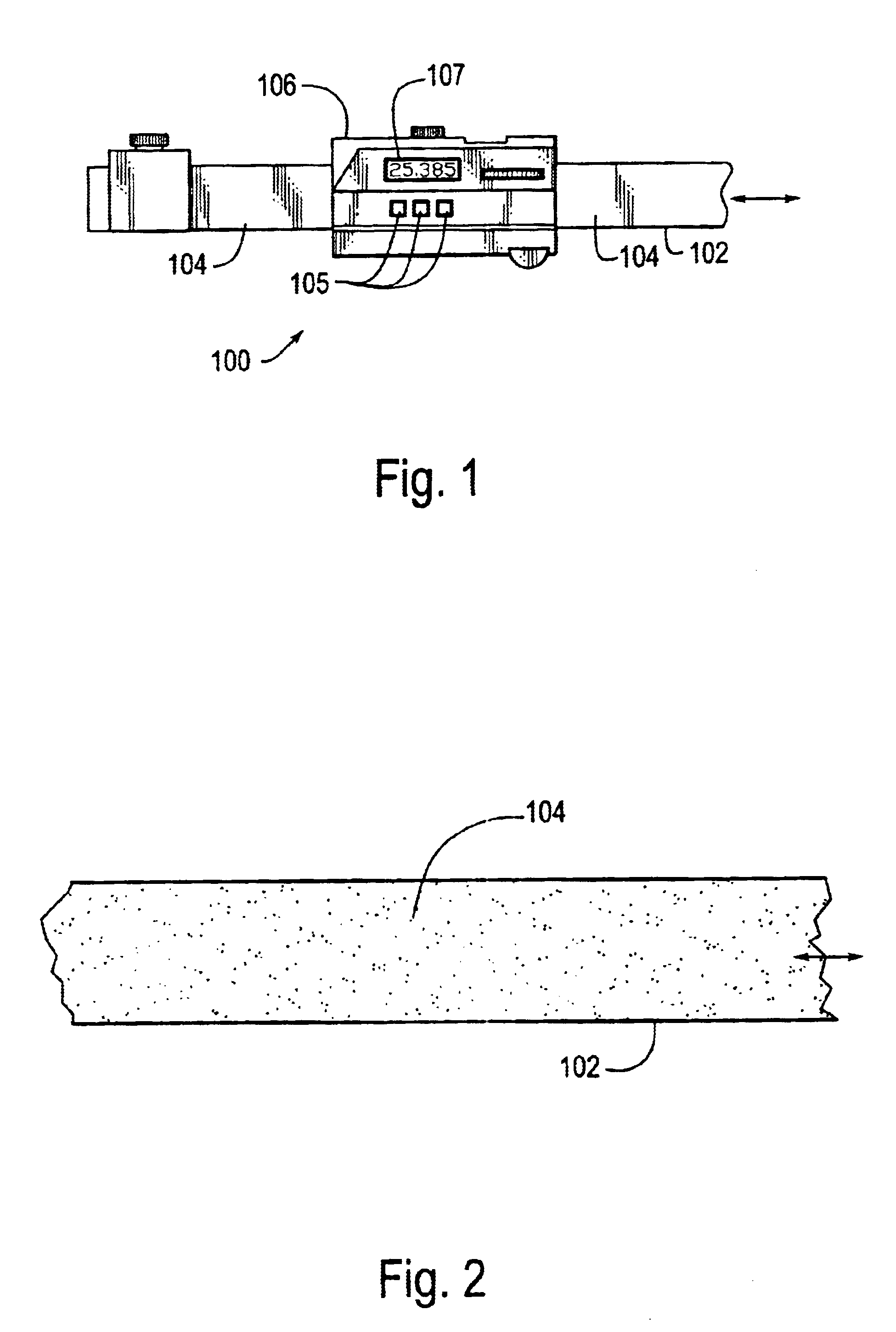
FIG. 1 is a plan view of a first exemplary embodiment of a position measuring device 100 incorporating a speckle-image-based optical position transducer according to this invention. As shown in FIG. 1, the position measuring device 100 includes a scale member 102 and a readhead assembly 106. In particular, an optically diffusing, or optical rough, surface 104 of the scale member 102 is positioned adjacent to an open, or illuminating, end of the readhead assembly 106. Another surface of the readhead assembly 106 includes a plurality of control buttons 105 and a position or displacement value display device 107.

In various exemplary embodiments, the display 107 is a liquid crystal display. However, the display 107 can be any known or later developed display device, including an LED display device or the like. The control buttons 105 include a millimeter / inch toggle button, and on / off button, and a set zero position button. The millimeter / inch toggle button 105 toggles the display betwe...


PUM


Abstract

A speckle readhead includes a light source that outputs light towards an optically rough surface. Light scattered from this surface contains speckles. The scattered light is imaged onto an image detector, captured and stored. Subsequently, a second image is captured and stored. The two images are repeatedly compared at different offsets in a displacement direction. The comparison having the highest value indicates the amount of displacement between the readhead and the surface that occurred between taking the two images. An optical system of the readhead includes a lens and an aperture. The aperture can be round, with a diameter chosen so that the average size of the speckles is approximately equal to, or larger than, the dimensions of the elements of the image detector. The dimension of the aperture in a direction perpendicular to the direction of displacement can be reduced. Thus, the imaged speckles in that direction will be greater than the dimension of the image detector elements in that direction. Such a readhead is relatively insensitive to lateral offsets. The lens can be a cylindrical lens that magnifies the relative motion along the direction of displacement but does not magnify relative motions in the direction perpendicular to the direction of displacement. The optical system can also be telecentric. Thus, the readhead is relatively insensitive to both separation and relative motions between the readhead and the surface. The light source can be modulated to prevent smearing the speckles across the image detector. The light source can be strobed to freeze the image.

Description

1. Field of InventionThis invention is directed to transducing positional displacements using speckle-image-correlation.2. Description of Related ArtVarious known devices use speckle images and correlation between speckle images to determine deformations and / or displacements. A speckle image is generated by illuminating an optically rough surface with a light source. Generally, the light source is a coherent light source, and more particularly, is a laser-generating light source, such as a laser, a laser diode, and the like. After the optically rough surface is illuminated by the light source, the light scattered from the optically rough surface is imaged onto an optical sensor, such as a charge-coupled device (CCD), a semi-conductor image sensor array, such as a CMOS image sensor array, or the like.Prior to displacement or deformation of the optically rough sensor, a first speckle image is captured and stored. Subsequently, after deformation or displacement of the optically rough s...

Claims


Application Information

Patent Timeline
Patent Type & Authority Patents(United States)
IPC IPC(8): G01B3/20G01D5/26G01D5/347G01B11/00
CPCG01B3/205G01D5/34715G01D5/347G01B11/002
Inventor NAHUM, MICHAEL M.MASRELIEZ, KARL G.
Owner MITUTOYO CORP
Why Eureka
Try Eureka