Thermal interface material having a zone-coated release linear

a technology of thermal interface material and zone coating, which is applied in the direction of film/foil adhesive, semiconductor/solid-state device details, lighting and heating apparatus, etc., can solve the problems of increasing complexity of circuit design, increasing design complexity, and shrinking of device size and other issues

Inactive Publication Date: 2003-11-11
PARKER HANNIFIN CORP
View PDF94 Cites 130 Cited by
  • Summary
  • Abstract
  • Description
  • Claims
  • Application Information

AI Technical Summary

Benefits of technology

The present invention is directed to a thermal management materials, and particularly to release liners for tapes and pads of such materials which are adhered to the heat transfer surface of a heat sink or spreader prior to its installation in an electronic device. In accordance with the precepts of the invention, the liner is provided as having one or more first zones exhibiting a given first release value or peel strength relative to the interface material, and one or more second zones bordered by the first zones which exhibit a second release value or peel strength which is lower than that of the first zones. The ratio of the surface area of the first zone or zones to that of the second zone or zones, which typically will be between about 10-90% for most applications, may be selected to a effect an overall balanced release value for the liner. When employed, for example, as a protective liner for pads of thermal interface materials adhered to the heat transfer surface of a heat sink, heat spreader, or the like, such liner substantially reduces the occurrence of premature separation during shipping, handling, or storage of the part. However, prior to the installation of the part, the liner may be controllably removed from the interface pad without evident adhesive or cohesive failure.
Although not always required, a carrier or reinforcement member (not shown) optionally may be incorporated within layer 52 as an interlayer. Conventionally, such member may be provided as a film formed of a thermoplastic material such as a polyimide, a layer of a woven fiberglass fabric or cloth, or an aluminum or other metal foil, screen, or expanded mesh. Such reinforcement improves the physical strength of the layer 52 to facilitate its handling at higher ambient temperatures and its die cutting into a variety of geometries. The reinforcement member typically will have a thickness of between about 0.5-5 mil (12.5-125 .mu.m), with a thickness of about 2 mil (50 .mu.m) being preferred for metal foils.
Unlike conventional greases or waxes, PCM layer 52 advantageously is form-stable at normal room temperature such that pad 50 may be shipped and handled without causing the PCM to slump, sag, or run. For automated application, pad 50 may be supplied as a roll of tape by applying a film of PCM layer 52 to a length of the zone coated release liner 10 using a conventional coating process. A solvent, diluent, or other vehicle may be provided to lower the viscosity of the PCM. After the PCM layer 52 has been applied, the coated release liner 10 may be dried to flash the solvent and leave an adherent, susbstantially non-tacky film, coating, or other residue of the PCM thereon.

Problems solved by technology

Circuit designs for modern electronic devices such as televisions, radios, computers, medical instruments, business machines, communications equipment, and the like have become increasingly complex.
Although the complexity of the designs has increased, the size of the devices has continued to shrink with improvements in the ability to manufacture smaller electronic components and to pack more of these components in an ever smaller area.
As electronic components have become smaller and more densely packed on integrated boards and chips, designers and manufacturers now are faced with. the challenge of how to dissipate the heat which is ohmicly or otherwise generated by these components.
Indeed, it is well known that many electronic components, and especially power semiconductor components such as transistors and microprocessors, are more prone to failure or malfunction at high temperatures.
Thus, the ability to dissipate heat often is a limiting factor on the performance of the component.
For high power circuits and the smaller but more densely packed circuits typical of current electronic designs, however, simple air circulation often has been found to be insufficient to adequately cool the circuit components.
These pockets reduce the overall surface area contact within the interface which, in turn, reduces the heat transfer area and the overall efficiency of the heat transfer through the interface.
Moreover, as it is well known that air is a relatively poor thermal conductor, the presence of air pockets within the interface reduces the rate of thermal transfer through the interface.
The greases and waxes of the aforementioned types heretofore known in the art, however, generally are not self-supporting or otherwise form stable at room temperature and are considered to be messy to apply to the interface surface of the heat sink or electronic component.
Moreover, use of such materials typically involves hand application or lay-up by the electronics assembler which increases manufacturing costs.
That is, if the liner is too loose, there is the potential that it may separate from the pad during shipping or handling and thereby subject the compound layer to the risk of contamination or other damage.
However, if the liner is too tight, it may be difficult to remove without splitting the compound or lifting the pad from the heat transfer surface.
With respect to the thermal interface materials herein involved, however, it has been observed in some circumstances that the coated release liners or uncoated fluoropolymer or silicone films heretofore known in the art have proved too loose to assure no premature separation from the material pad.
Likewise, with respect to other uncoated release liners heretofore known in the art, it has been observed in some circumstances that such liners have proved too tight resulting in adhesive or cohesive failure of the pad.

Method used


Image

  • Thermal interface material having a zone-coated release linear
  • Thermal interface material having a zone-coated release linear
  • Thermal interface material having a zone-coated release linear

Examples


example 1

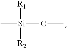
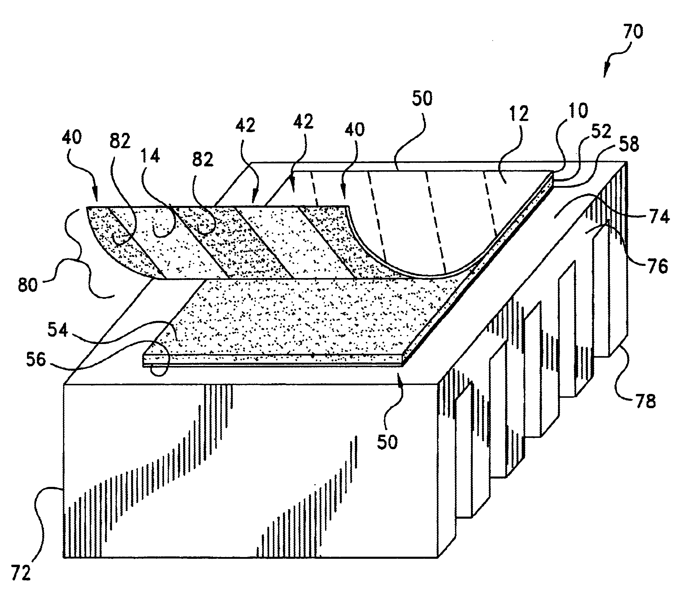
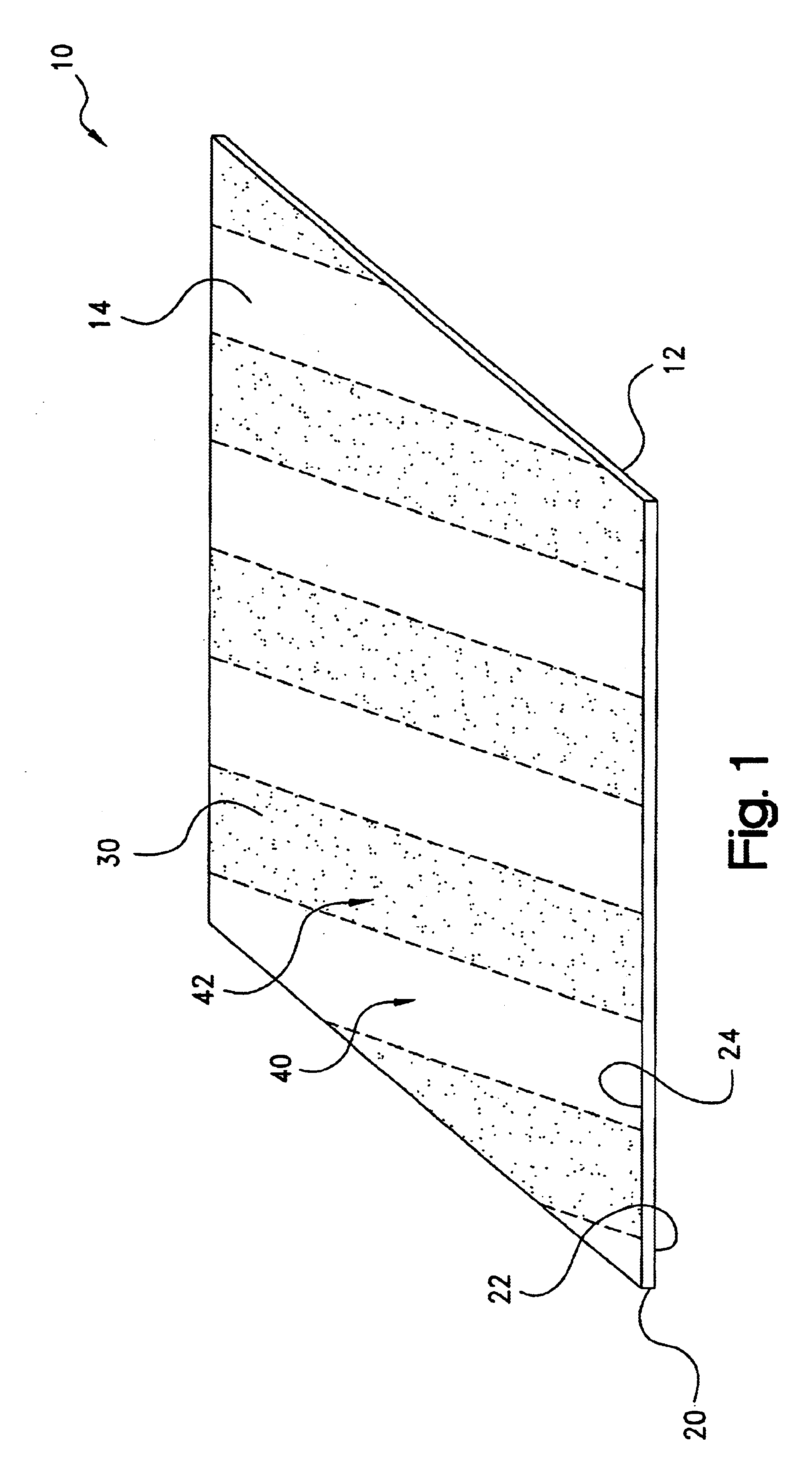
A platinum-cured silicone release coating (Dow Corning Corp., Midland, Mich.) was selected for use in demonstrating the feasibility of the zone-coated release liners of the present invention. The coating was formulated as follows:

Zone coated liner sheets were prepared by cutting 1 / 8-inch strips of 4 mil low tack vinyl tape (Semiconductor Equipment Corp., Moorpark, Calif.) and manually applying the strips to a 2 mil thick polyester film (The Pilcher Hamilton Co., Hinsdale, Ill.). The strips were spaced about 1 / 8-inch apart.

A solution of the release coating adjusted to 5% solids was applied to the liner sheets using an EZ Coater Drawdown machine and a #6 wire rod. The wet samples were immediately placed into a 225.degree. F. oven for 5 minutes to evaporate the solvent and to initiate curing. After drying, the tape strips were removed and the silicone zones were checked for sharpness by running a 48 dye pen across the film. The dye was observed to wet the untreated zones and to bead on...

example 2

In order to simulate a typical end use application, an application test was developed which was used to assess the performance of die cut pieces with manual liner removal. A 0.5 mil layer of an acrylic PSA was transfer coated to the thermal compound side of the laminated samples of Example 1. One inch square pieces were cut from the PSA-coated samples, and the zone orientation was noted. The adhesive side of the samples was applied to a steel panel, which then was cycled to 110.degree. F. for one hour and equilibrated to room temperature for two hours. Thereafter, liner removal was evaluated by manually pulling the liner from the thermal compound. Lift-off and compound splitting were evaluated and recorded on 20 sample pieces of machine, transverse and 45.degree. zones oriented in the pull direction.

The test results are shown in Table 3. Untreated polyester film was used as a control and compared to fully coated samples and machine direction, transverse, and 45.degree. zone coated s...


PUM

PropertyMeasurementUnit
particle sizeaaaaaaaaaa
clamping pressuresaaaaaaaaaa
thickaaaaaaaaaa

Abstract

A release liner particularly adapted for use with a layer of a thermal interface material having a first surface and a second surface which is bondable to the heat transfer surface of a thermal dissipation member. The liner has an exterior surface and an interior surface disposable in adhering contact with the first surface of the thermally-conductive material. The liner interior surface has one or more first zones defined thereon which exhibit a first release value relative to the first surface of the thermally-conductive material, and one or more second zones bordered by the first zones which exhibit a second release value relative to the first surface of the thermally-conductive material which is lower than the first release value of the first zones. With the second surface of the thermally-conductive material being bonded to the heat transfer surface of the thermal dissipation member, the release liner is removable from the first surface of the thermally-conductive material without substantial cohesive or adhesive failure thereof.

Description

The present invention relates broadly to thermal management materials for electronic devices. Such materials commonly are used as heat transfer interfaces between, for example, the mating heat transfer surfaces of a heat-generating, electronic component, such as an integrated circuit (IC) chip, and a thermal dissipation member, such as a heat sink, for the conductive cooling of the electronic component. More particularly, the present invention relates to a release liner for tapes and pads of such materials which are adhered to the heat transfer surface of the heat sink prior to the installation of the heat sink in the electronic device. In accordance with the invention, such liner is zone-coated with a release agent to provide a controlled release value or peel strength. When the liner is used as a protective sheet for the exterior surface of a pad which is adhered to the heat sink, such zone coating assists in assuring that the liner remains affixed to the pad so that the heat sink...

Claims


Application Information

Patent Timeline
Patent Type & Authority Patents(United States)
IPC IPC(8): C09J7/02H01L23/373H01L23/34H05K7/20
CPCC09J7/0232H01L23/3735H01L23/3737H05K7/20481H01L24/29H01L2924/09701H01L2924/3011H01L2224/32245H01L2924/0002H01L2224/29386H01L2224/29076H01L2224/2929H01L2924/00C09J7/403H01L2924/14
Inventor BERGIN, JONATHAN M.
Owner PARKER HANNIFIN CORP
Why Eureka
Try Eureka