
Silicon nitride sintered material and production process thereof

a technology of silicon nitride and sintered material, which is applied in the direction of mechanical equipment, machines/engines, light and heating equipment, etc., can solve the problems of reducing affecting the service life of the sintered material,

Inactive Publication Date: 2003-12-02
NGK SPARK PLUG CO LTD
View PDF20 Cites 23 Cited by
  • Summary
  • Abstract
  • Description
  • Claims
  • Application Information

AI Technical Summary

Benefits of technology

The present inventors have performed studies on the relation of components of silicon nitride sintered material and amounts thereof vs. insulating property and thermal expansion coefficient thereof; and have found that when the amount of a rare earth element as reduced to a certain oxide thereof, the element being contained in the sintered material, is determined so as to fall within a specific range, and when the ratio by mol of subtraction remainder oxygen amount as calculated in relation to the oxygen contained in the sintered material, the remainder oxygen amount being expressed in terms of silicon dioxide, to the amount of oxygen contained in the sintered material is determined so as to fall within a specific range, the silicon nitride sintered material has a high thermal expansion coefficient, and exhibits excellent anti-corrosion property and mechanical characteristics. The present invention has been accomplished on the basis of this finding.
In the silicon nitride sintered material of the present invention, examples of the aforementioned "Group 4a through 6a element" include Ti, Ta, Mo, W, and Cr. Of these, Cr is particularly preferred. No particular limitation is imposed on the amount of the Group 4a through 6a element contained in the sintered material, and the amount of the Group 4a through 6a element is usually 5-13.5 mass %, preferably 6-10 mass %, more preferably 6.5-10 mass %, as reduced to a certain oxide thereof. When the amount of the element falls within the above ranges, the mechanical characteristics at high temperatures can be improved.
Examples of the aforementioned "rare earth element" contained in the silicon nitride sintered material of the present invention include Eu, Sm, Y, Sc, La, Ce, Pr, Nd, Gd, Tb, Dy, Er, and Yb. In the sintered material of the present invention, the aforementioned "the amount of the rare earth element as reduced to a certain oxide thereof" is usually 5.7-10.3 mol %, preferably 6-9.5 mol %, more preferably 6-9 mol %. When the amount of the rare earth element as reduced to a certain oxide thereof is less than 5.7 mol %, since the thermal expansion coefficient of the silicon nitride sintered material decreases, cracks are generated in an insulating material as a result of the difference in thermal expansion coefficient between the insulating material and a resistance heater during application of heat or generation of heat, which is not preferable. In contrast, when the amount of the rare earth element as reduced to a certain oxide thereof exceeds 10.3 mol %, the anti-corrosion property and flexural strength of the silicon nitride sintered material are impaired, which, again, is not preferable. As used herein, "the amount of a rare earth element as reduced to a certain oxide thereof" refers to the amount of a rare earth element contained in the sintered material as reduced to RE.sub.2 O.sub.3 (RE: rare earth element). The rare earth element content is 15-26 mass %, preferably 15-25 mass %, more preferably 16-24 mass %, much more preferably 17-24 mass %, as reduced to a certain oxide thereof. When the rare earth element content falls within the above ranges, the mechanical characteristics at high temperatures can be improved.
No particular limitation is imposed on the amount of the aforementioned "silicon carbide" contained in the silicon nitride sintered material of the present invention, but the amount is usually 0.8-3 mass %, preferably 1-3 mass %, more preferably 1.5-2.5 mass %. When the amount falls within the above ranges, lowering of insulation resistance, which is attributed to conductivity of silicon carbide, is prevented. In addition, aciculation of particles of silicon nitride, which is an insulating substance, is prevented, and therefore the specific surface area of the silicon nitride particles increases, resulting in prevention of formation of paths for conduction of electricity by conductive particles of a high thermal expansion coefficient compound.

Problems solved by technology

When silicon nitride sintered material is used as an insulating material, a problem arises in that cracks are possibly generated in the insulating material during application or generation of heat, because silicon nitride has a thermal expansion coefficient lower than that of tungsten, tungsten carbide, molybdenum silicide, or a similar substance that is generally employed as a resistance heater (i.e. a resistance heating element) embedded in the insulating material.
Therefore, use of the sintered material as an insulating material for ceramic heaters is problematic.
However, obtaining silicon nitride sintered material having a high thermal expansion coefficient while maintaining excellent anti-corrosion property has remained difficult so far.
Other crystalline phases such as mono-silicate phase (RESiO.sub.5) not containing oxy-nitrogen do not aggravate the corrosion resistance.
C. When the thermal expansion coefficient is less than 3.7 ppm / .degree. C., in a case where the sintered material is used as an insulating material such as a base material of ceramic glow plugs, cracks are generated in the insulating material during application or generation of heat, because of poor thermal expansion of the sintered material, and such cracks are attributed to the difference in thermal expansion coefficient between the insulating material and a resistance heater formed from tungsten, tungsten carbide, molybdenum silicide, or similar mater

Method used


Image

  • Silicon nitride sintered material and production process thereof
  • Silicon nitride sintered material and production process thereof
  • Silicon nitride sintered material and production process thereof

Examples


Embodiment Construction

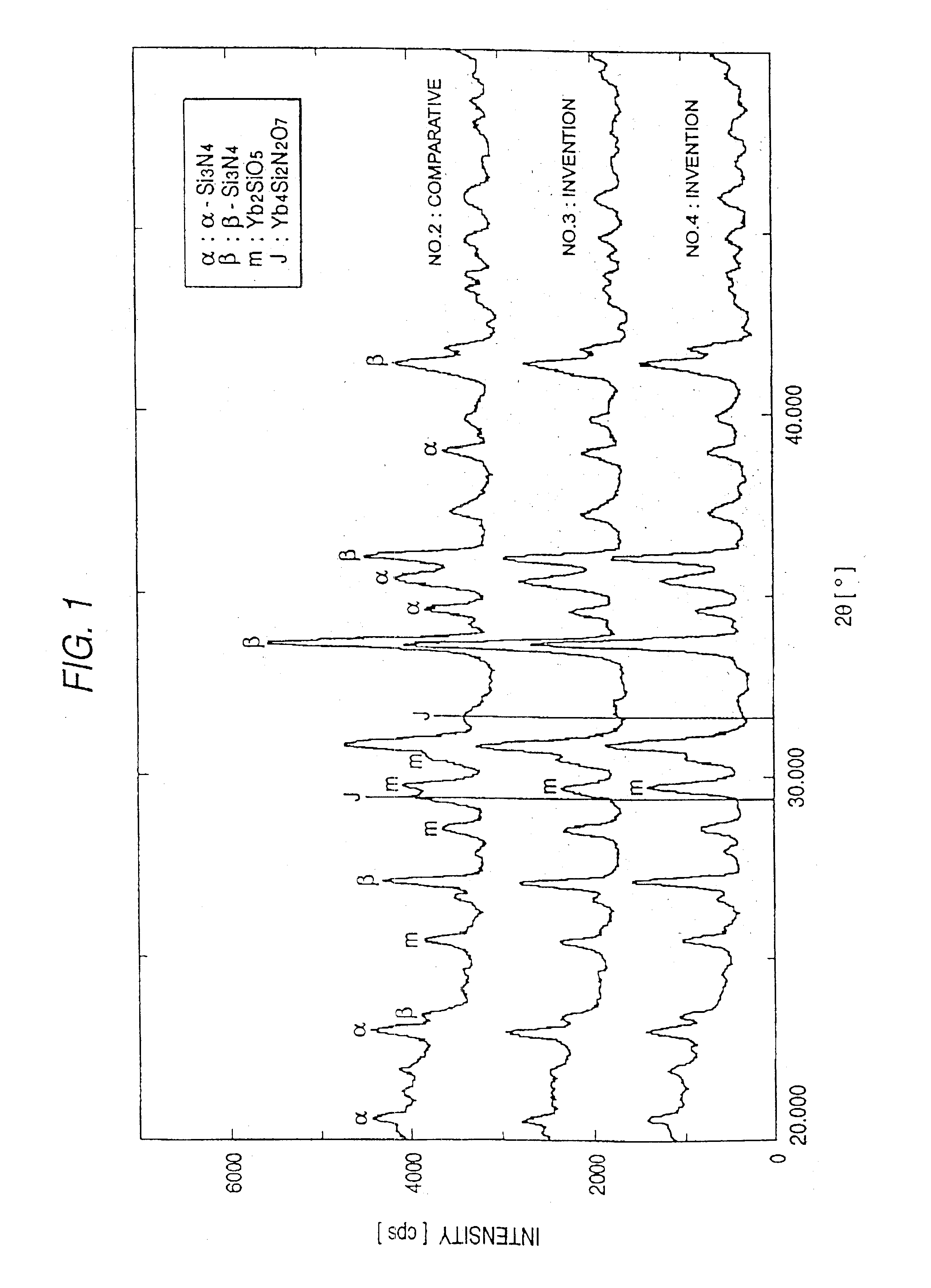
As is apparent from FIG. 1, the peak of the J phase is not observed in X-ray charts of the silicon nitride sintered materials Nos. 3 and 4, which within the scope of the present invention, whereas the peak of the J phase is observed in the X-ray chart of the sintered material No. 2, which falls outside the scope of the present invention; i.e., the J phase (crystalline phase)) is generated in the sintered material No. 2. In FIG. 1, m represents a crystalline phase of mono-silicate (:Yb.sub.2 SiO.sub.5) that does not aggravate the high temperature corrosion resistance of the sintered silicon nitride.

As is apparent from Tables 1 and 2, in the sintered materials Nos. 14 and 15, in which the rare earth element oxide content is as high as 10.5 mol % (27.0 mass % or more), the J phase (crystalline phase) is generated, and increases in the weight through oxidation are as high as 0.15 mg / cm.sup.2 and 0.08 mg / cm.sup.2, respectively. Briefly, the sintered materials Nos. 14 and 15 exhibit poor ...


PUM

PropertyMeasurementUnit
flexural strengthaaaaaaaaaa
particle sizeaaaaaaaaaa

Abstract

A silicon nitride sintered material containing silicon nitride, a Group 4a through 6a element, a rare earth element, and silicon carbide, characterized in that the amount of the rare earth element as reduced to a certain oxide thereof is 5.7-10.3 mol %; the ratio by mol of subtraction remainder oxygen amount calculated in relation to the oxygen contained in the sintered material, the remainder oxygen amount being expressed in terms of silicon dioxide, to the amount of oxygen contained in the sintered material is at least 0.50 and less than 0.70; a four-component crystalline phase of rare earth element-silicon-oxygen-nitrogen is not present; and the thermal expansion coefficient is at least 3.7 ppm / ° C. between room temperature and 1,000° C.

Description

1. Field of the InventionThe present invention relates to a silicon nitride sintered material and to a production process thereof, and more particularly to a silicon nitride sintered material which exhibits excellent mechanical characteristics and anti-corrosion property, which has a high thermal expansion coefficient, and which has high heat resistance so as to make the sintered material suitable for use as an insulating material such as a base material used in a ceramic glow plugs, as well as to a production process thereof.2. Description of the Related ArtSilicon nitride sintered material, having excellent mechanical characteristics and heat resistance, has been employed as an insulating material for use in ceramic heaters in which a resistance heater is embedded or for use in similar products. In this case, increase in the weight of silicon nitride sintered material through oxidation is desired as low as possible, so that the sintered material attains excellent anti-corrosion pr...

Claims


Application Information

Patent Timeline
Patent Type & Authority Patents(United States)
IPC IPC(8): C04B35/584F02P19/00F23Q7/00
CPCC04B35/584F23Q7/001F23Q2007/004
Inventor FUNAKI, KOUJIMATSUBARA, KATSURAWATANABE, HIROKIITO, MASAYA
Owner NGK SPARK PLUG CO LTD
Learn More