The continuous roll motion of the camera facilitates image collection without large inertial accelerations and decelerations or large power spikes, as are found in prior art step frame camera
system when the camera mass is physically stepped across the
terrain of interest in a series of start and stop movements. The present invention is believed superior to prior art step framing cameras since the problems inherent with mechanical stepping are eliminated. The camera and method are applicable to all sizes and arrangements of cameras, including cameras implementing single spectrum, multi-spectrum and hyperspectral optical systems. The invention is also applicable to cameras with mechanical shutters, electronic shutters, acoustical / optical switches, and other electronic
exposure controls.
In another aspect of the invention, an electro-optical roll framing camera with electronic roll motion compensation is provided. The camera is adapted for installation in an
aerial reconnaissance vehicle. The camera comprises an electro-
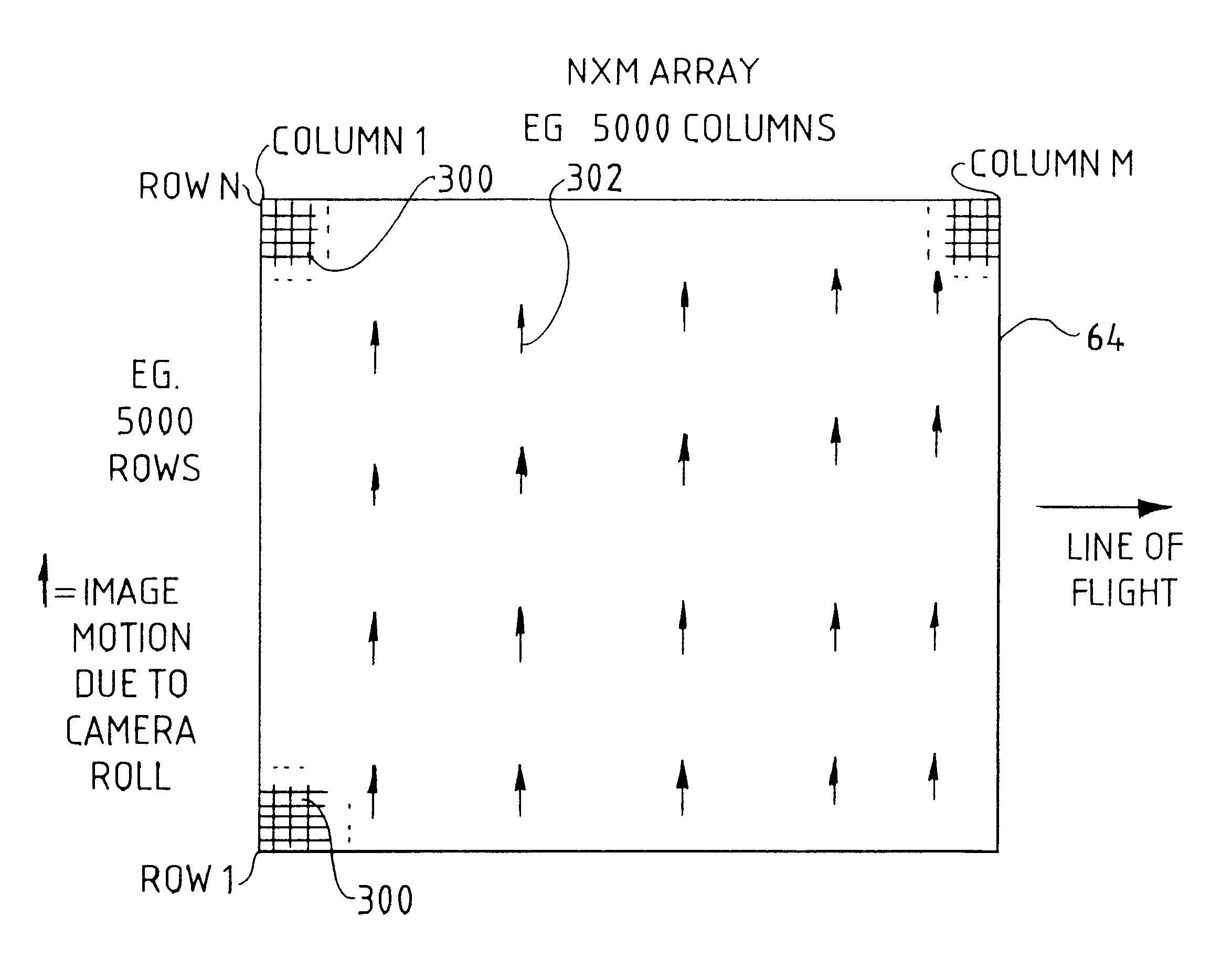
optical detector comprising a two-dimensional array of photosensitive cells that store pixel information. The array is arranged in a plurality of rows and columns and has at least one readout register for reading out pixel information from the array. The camera further includes an optical
system directing scene
radiation onto the array. A
servo-
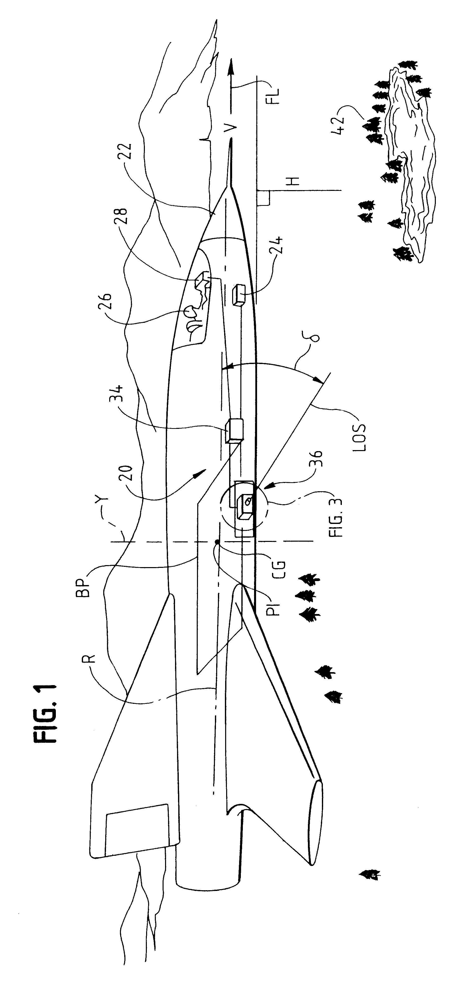
mechanical system is provide which couples the camera to the aerial reconnaissance vehicle which is adapted or configured for continuously rolling the camera about a rotation axis to thereby direct scene information onto the optical system and array. Further, roll motion compensation circuitry is provided for electronically transferring pixel information in the array of photosensitive cells at a rate substantially matching the rate of image motion due to the rotation of the camera, whereby the resolution of images generated by said array may be preserved.
In the preferred embodiment, the
servo-mechanical subsystem also includes a second
motor system coupled to the Cassegrain optical system. The second
motor system rotates the Cassegrain optical system about a second axis in the direction of forward motion of the reconnaissance vehicle to compensate for forward motion of the aerial reconnaissance vehicle. The action of the first motor
assembly to rotate the entire camera housing about the roll axis occurs at the same time (i.e., simultaneously with) the action of the second
motor system to rotate the Cassegrain optical system in the line of flight to accomplish forward motion compensation. The net effect of the action of the second motor system and the roll motion compensation system is that the image of the scene of interest is essentially frozen in the focal plane while the
image recording media obtain the frames of imagery, allowing
high resolution images of the scene to be obtained.
The present invention required the solution to several difficult technical challenges, including optical,
servo-mechanical and operational difficulties. For an electro-optical framing LOROP camera to operate in a continuous sweep with a framing array with at least two discrete bands of the
electromagnetic spectrum at the same time, the challenge is to accurately compensate for the roll motion electronically at a
focal plane detector with (1)
good image quality and satisfactory
modulation transfer function, (2) while minimizing inertial loading, and (4) enabling the use of a relatively large two-dimensional area array as a
focal plane detector to get an adequate field of view and resolution. In accordance with one aspect of the invention, these optical challenges were solved by an on-
chip roll motion compensation described in more detail herein.
This servo-mechanical situation required a unique inventive solution, described in detail herein. The solution, as provided in one aspect of the present invention, was to (1) rotate the entire camera (including the entire optical system and the
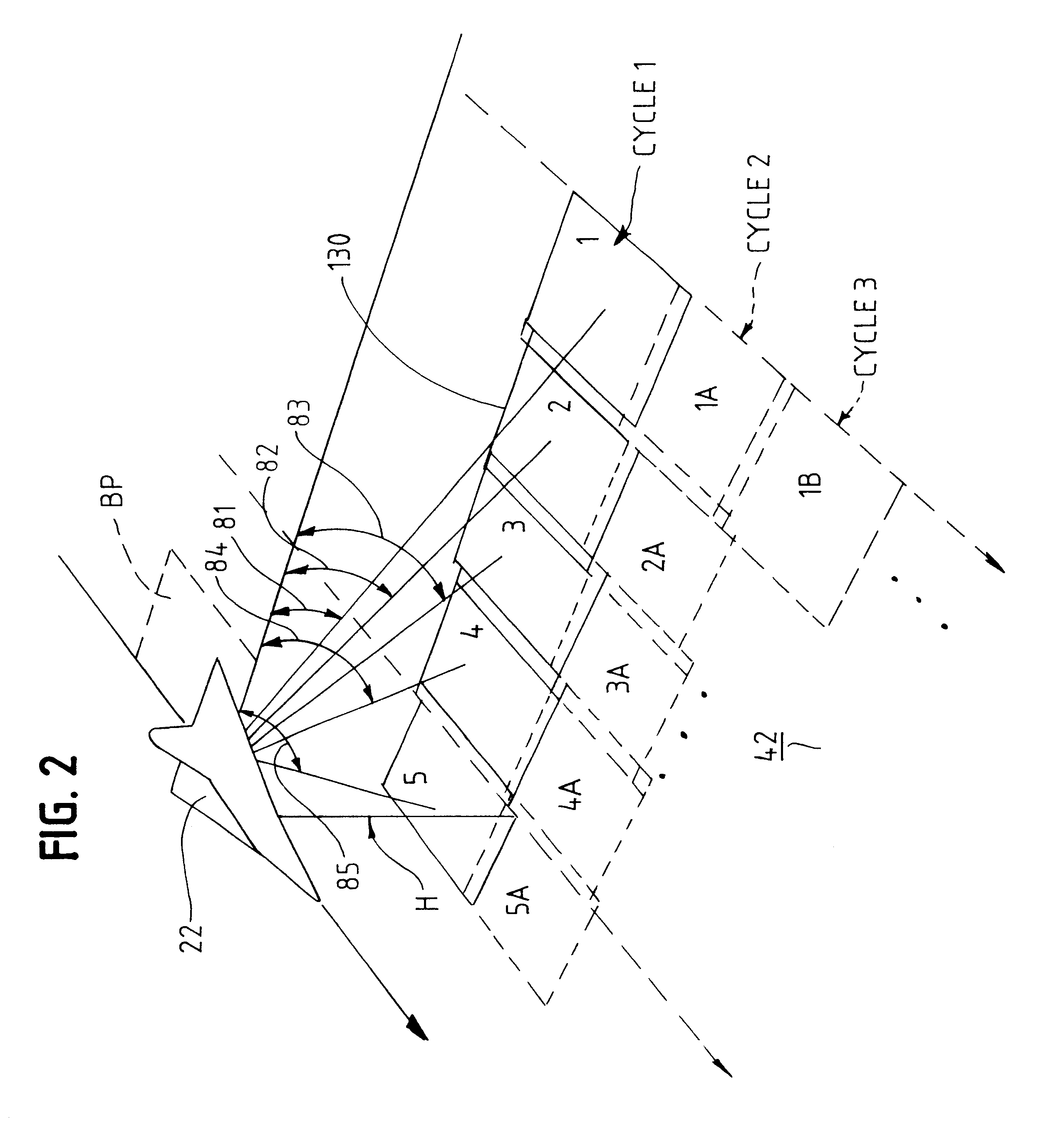
image recording media) smoothly in a continuous fashion about an axis parallel to the aircraft roll axis, similar to the pan-type movement, but without the starts and stops used in a traditional step-frame camera system, and (2) operating the camera as a framing camera while the camera undergoes the smooth rotation. Frames of imagery are thus taken while the camera smoothly rotates about the roll axis at a
constant angular velocity. In addition to this novel "roll-framing" technique, the present invention also electronically compensates for, i.e., stops, the image motion due to roll while the camera is scanning in a smooth motion. Meanwhile, a novel forward motion compensation technique is performed by the Cassegrain optical assembly to cancel out image motion effects due to the forward motion of the aircraft. The result enables exposures of the
image recording media to the scene while compensating for roll and forward motion, enabling high-resolution images to be obtained.

