Simplified flexible electrostatographic imaging member belt

a flexible, electrostatographic technology, applied in the direction of electrographic process apparatus, instruments, corona discharge, etc., can solve the problems of deterioration in physical condition, and deformation of image quality during extended cycling, and achieve simple material structure, excellent electrostatic latent image, and simple material configuration

Inactive Publication Date: 2003-12-09
XEROX CORP
View PDF6 Cites 37 Cited by
  • Summary
  • Abstract
  • Description
  • Claims
  • Application Information

AI Technical Summary

Benefits of technology

An advantage of the present invention is to provide improved methodology for fabricating multiple layered imaging member webstocks which overcomes curling of the multiple layers.
is to provide improved methodology for fabricating multiple layered imaging member webstocks which overcomes curling of the multiple layers.
The present invention provides an improved process for imaging member webstock fabrication having a simplified material configuration.
Electrostatographic flexible imaging members are well known in the art. Typical flexible electrostatographic imaging members include, for example, (1) photosensitive members (photoreceptors) commonly utilized in electrophotographic processes and (2) electroreceptors such as ionographic imaging members for electrographic imaging systems. The flexible electrostatographic imaging members may be seamless or seamed belts. Electrophotographic imaging member belts comprise a charge transport layer and a charge generating layer on one side of a supporting substrate layer and an anticurl backing layer coated on the opposite side of the substrate layer. Some electrographic imaging member belts have a more simple material structure comprising a dielectric imaging layer on one side of a supporting substrate and an anticurl backing layer on the opposite side of the substrate.
Electrophotographic flexible imaging members may comprise a photoconductive layer comprising a single layer or composite layers. Typical electrophotographic imaging members exhibit undesirable imaging member curling and require an anticurl backing layer. The anticurl backing layer is provided to prevent the multiple layers of an imaging member from curling and thereby keeping the member flat. One type of composite photoconductive layer used in electrophotography is illustrated in U.S. Pat. No. 4,265,990, which describes a photosensitive member having at least two electrically operative layers. One layer comprises a photoconductive layer which is capable of photogenerating holes and injecting the photogenerated holes into a contiguous charge transport layer. Generally, where the two electrically operative layers are supported on a conductive layer with the photoconductive layer sandwiched between the contiguous charge transport layer and the conductive layer, the outer surface of the charge transport layer is charged with a uniform charge of a negative polarity and the supporting electrode is utilized as an anode. The supporting electrode may still function as an anode when the charge transport layer is sandwiched between the supporting electrode and the photoconductive layer. The charge transport layer in this latter embodiment is capable of supporting the injection of photogenerated electrons from the photoconductive layer and transporting the electrons through the charge transport layer. Photosensitive members having at least two electrically operative layers, as discussed above, provide excellent electrostatic latent images when charged with a uniform negative electrostatic charge, exposed to a light image and thereafter developed with finely divided electroscopic marking particles. The resulting image is transferable to a receiving member such as paper.
As more advanced, higher speed electrophotographic copiers, duplicators and printers were developed, degradation of image quality was encountered during extended cycling. Moreover, complex, highly sophisticated duplicating and printing systems operating at very high speeds have placed stringent requirements including narrow operating limits on photoreceptors. For flexible electrophotographic imaging members having a belt configuration, the numerous layers found in modern photoconductive imaging members are highly flexible, adhere well to adjacent layers, and exhibit predictable electrical characteristics within narrow operating limits to provide excellent toner images over many thousands of cycles. One type of multilayered photoreceptor that has been employed as a belt in negatively charging electrophotographic imaging systems consists of a substrate, a conductive layer, a blocking layer, an adhesive layer, a charge generating layer, a charge transport layer, and a conductive ground strip layer adjacent to one edge of the imaging layers. This photoreceptor belt may also comprise an additional layer such as an anticurl backing layer to achieve the desired imaging member belt flatness.

Problems solved by technology

Typical electrophotographic imaging members exhibit undesirable imaging member curling and require an anticurl backing layer.
As more advanced, higher speed electrophotographic copiers, duplicators and printers were developed, degradation of image quality was encountered during extended cycling.
Moreover, complex, highly sophisticated duplicating and printing systems operating at very high speeds have placed stringent requirements including narrow operating limits on photoreceptors.
This repetitive imaging member belt cycling leads to a gradual deterioration in the physical and mechanical integrity of the exposed outer charge transport layer leading to premature onset of fatigue charge transport layer cracking.
The cracks developed in the charge transport layer as a result of dynamic belt fatiguing are found to manifest themselves into copy print out defects which thereby adversely affect the image quality on the receiving paper.
In essence, the appearance of charge transport cracking cuts short the imaging member belt's intended functional life.
Since the charge transport layer in a typical prior art photoreceptor device has a coefficient of thermal contraction approximately 31 / 2 times larger than the substrate support, the charge transport layer, upon cooling down to room ambient, results in greater dimensional contraction than that of the substrate support causing photoreceptor curling.
Although it has been desirable to have the anticurl backing layer to complete a photoreceptor web stock material package, an anticurl backing layer application represents an additional coating step increasing labor and material cost, which can result in a decrease of daily photoreceptor production through-put of about 25%.
Moreover, sending the photoreceptor web stock back to the coater immediately after coating the charge transport layer for anticurl backing layer application has frequently resulted in photoreceptor production yield lost due to web stock scratching caused by handling.
This internal built-in strain exacerbates the fatigue charge transport layer failure and promotes the onset of charge transport layer cracking.
Imaging members having an anticurl backing layer not only require one addition coating step to complete the finish production, but also create an environmental issue involving solvent emission release to the atmoshere.
Also, due to the presence of bubbles, a weakening of the layer and onset of mechanical failure can occur when fatigue tension / compression strain is repeatedly applied to the anticurl backing layer during machine cycling, particularly when cycling around small diameter support rollers.
Further, when rear erase is employed to discharge the photoreceptor belt during electrophotographic imaging processes, the presence of bubbles causes a light scattering effect which leads to undesirable non-uniform discharge.
Also, the presence of bubbles in the anticurl backing layer during seam welding processes can cause the bubbles to expand and form splashings exhibiting open pits.
During electrophotographic imaging and cleaning cycles, these open pits can function as sites that trap toner, debris, and dirt particles making attempts to clean the imaging member belt extremely difficult.
It has also been found that, during imaging belt cycling, the trapped toner, debris, and dirt particles can be carried out by the cleaning blade from the pits to contaminate the vital imaging components such as the lenses, Hybrid Scavengeless Development subsystems (HSD), Hybrid Jumping Development subsystems (HJD) and, other subsystems, and can also lead to undesirable artifacts which form undesirable printout defects in the final image copies.
Another disadvantage of photoreceptors having an anticurl backing layer occurs under dynamic belt cycling function conditions.
The anticurl backing layer is in constant mechanical interaction with the machine belt support rollers and backer bars causing the anticurl backing layer to develop substantial premature wear problems.
Anticurl backing layer wear reduces the thickness of the anticurl layer and diminishes the desired flattening effect.
This loss of anticurl layer thickness results in non-uniform charging density at the photoreceptor belt surface under normal imaging processing conditions.
Although attempts have been made to overcome these problems, the solution of one problem often leads to the generation of additional problems.
For example, the selection of a supporting substrate, for example, polyether sulfone or MAKROFOL.RTM. having thermal contraction matching with that of the MAKROFOL.RTM. found in the coated charge transport layer to effect the suppression of electrophotographic imaging member curling, has been observed to be susceptible to attack and damage by solvents used in the charge transport layer coating solution, rendering the imaging member useless.
Other substrate supports, having good thermal contraction matching properties such as TEDLAR or MELINAR, though yielding curl-free electrophotographic imaging members without anticurl back coating, have inherently low Glass Transition Temperatures (Tg), and were judged not suitable for imaging member fabrication.
Application a biaxial tensioning stress onto imaging members maintained at an elevated temperature slightly above the Glass Transition Temperature (Tg) of the charge transport layer was found to be a cumbersome batch process, which is very costly to implement in imaging member production.
Moreover, the large physical sizes of seam splashings 68 and 70, projecting outwardly over the two exterior surfaces 32 and 34, respectively, of the belt, are also problematic, because the bottom splashing 70 interacts physically with all the belt support rollers and the backer bars of the belt module to affect the imaging member belt's dedicate motion / transporting speed, while the top splashing 68 with a rough surface morphology 74 mechanically interferes with the cleaning blade sliding action to nick the blade and exacerbate blade wear as well causing it's the cleaning blades' premature loss of cleaning efficiency during electrophotographic imaging member belt machine function.
The amount of the debris, however, is beyond the removal capacity of the cleaning instrument.
As a consequence, the cleaning instrument dislodges the highly concentrated level of debris but cannot remove the entire amount during the cleaning process.
The upward movement of the flap presents an additional problem during the cleaning operation.
The flap becomes an obstacle in the path of the cleaning instrument as the instrument travels across the surface of the flexible imaging member seamed belt.
As the cleaning instrument strikes the flap, great force is exerted on the cleaning instrument which can lead to damage, e.g., excessive wear, nicking, and tearing of the cleaning blade.
Besides damaging the cleaning blade, the striking of the flap by the cleaning instrument causes unwanted vibration in the flexible imaging member seamed belt.
This unwanted vibration adversely affects the copy / print quality produced by the flexible imaging member seamed belt.
Tension stresses, such as that induced at the top belt surface 32, however, are a more serious problem.
These fatigue induced cracks in the coating layers of the imaging member seamed belt are seen to manifest themselves into copy printout defects.

Method used


Image

  • Simplified flexible electrostatographic imaging member belt
  • Simplified flexible electrostatographic imaging member belt
  • Simplified flexible electrostatographic imaging member belt

Examples


example vi

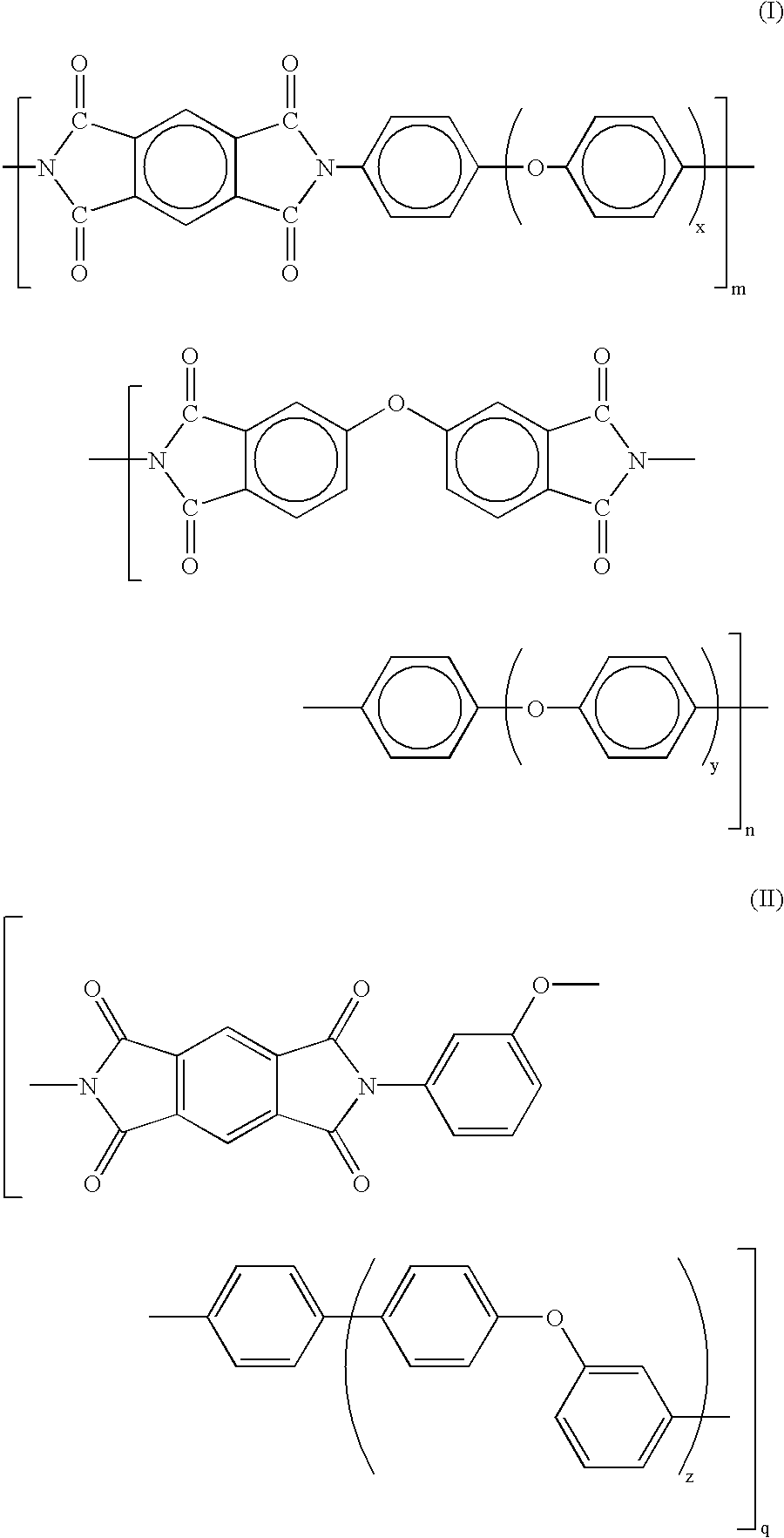
A flexible electrophotographic imaging member web stock was prepared in accordance to the procedures and using the same materials as those described in Comparative Example I, but with the exception that a 4-mil thick KAPTON KJ, a thermoplastic polyimide having a thermal contraction coefficient of 6.5.times.10.sup.-5 / .degree. C., a Glass Transition Temperature (Tg) of 210.degree. C., optical clarity from about 70% of the radiation wave length used for imaging member belt erase to about 100% of the radiation wave length used for imaging member belt erase, and not subject to attack or adversely affected by methylene chloride (available from E. I. Du Pont de Numours and Company), was chosen for the Polyester substrate support layer 26 replacement. The molecular structure of this Polyimide is given in formula (I) below: ##STR4##

wherein,

x=2 and y=2; and m and n are as illustrated herein.

Since both the polyimide substrate support 26 and the CTL 16 had similar thermal contraction coefficie...

example vii

A flexible electrophotographic imaging member web stock was prepared in accordance to Invention Example VI, with the exception that an alternate 4-mil thick thermoplastic polyimide, IMIDEX, having a thermal contraction coefficient of 6.0.times.10.sup.-5 / .degree. C., a Glass Transition Temperature (Tg) of 230.degree. C., optical clarity from about 70% of the radiation wave length used for imaging member belt erase to about 100% of the radiation wave length used for imaging member belt erase, and not subject to attack or adversely affected by methylene chloride (available from West Lake Plastics Company), was selected for substrate support 26 replacement. The molecular structure of IMIDEX polyimide is shown in formula (II) below: ##STR5##

wherein,

z=1 and q as illustrated herein.

The fabricated flexible electrophotographic imaging member required no anticurl backing layer to render imaging member flatness.

Commercially available polyimides, such as KAPTON F, H, and R types available from...

example viii

The flexible electrophotographic imaging member web stocks of Comparative Example I and Examples VI and VII were each cut to precise dimensions of 440 mm width and 2,808 mm in length. The opposite ends of each cut imaging member sheet was secured to give 1 millimeter overlap and ultrasonically welded, utilizing 40 KHz horn frequency, in the long dimension, to form a seamed flexible imaging member belt for fatigue dynamic electrophotographic imaging test in a selected xerographic machine.

Prior to carrying out the dynamic cycling belt test, the seam splashings 68 and 70, like those shown in FIG. 2 for control imaging member belt prepared with prior art imaging member web stock of Comparative Example 1, were measured and determined with the use of a Wyko Gauxe NT-200 for physical dimensions to give an average splashing height of about 79 micrometers and with about 0.85 millimeter in width. By comparison, the splashings of seamed belts prepared from the imaging member web stocks of Inve...


PUM


Abstract

An electrostatographic imaging member having a substrate support material which eliminates the need for an anticurl backing layer, a substrate support layer and a charge transport layer having a thermal contraction coefficient difference in the range of from -2x10<->5 / ° C. to about +2x10<->5 / ° C. a substrate support material having a Glass Transition Temperature (Tg) of at least 100° C., wherein the substrate support material is not susceptible to attack from the charge transport layer coating solution solvent and wherein the substrate support material is represented by the two structural formulas below:wherein m, n, and q represent the degree of polymerization having a number from 10 to 300; and x, y, and z are integers; with x and y from 2 to 10 and z from 1 to 10. An electrostatographic imaging member containing this substrate support layer.

Description

BACKGROUND OF INFORMATION1. Field of the InventionThe present invention relates to imaging members and to the preparation of a structurally simplified imaging member which does not exhibit curling of the multilayered imaging member webstock after coating and drying of the charge transport layer.An advantage of the present invention is to provide improved methodology for fabricating multiple layered imaging member webstocks which overcomes curling of the multiple layers.The present invention provides an improved process for imaging member webstock fabrication having a simplified material configuration.2. Description of Related ArtElectrostatographic flexible imaging members are well known in the art. Typical flexible electrostatographic imaging members include, for example, (1) photosensitive members (photoreceptors) commonly utilized in electrophotographic processes and (2) electroreceptors such as ionographic imaging members for electrographic imaging systems. The flexible electros...

Claims


Application Information

Patent Timeline
Patent Type & Authority Patents(United States)
IPC IPC(8): G03G5/147G03G5/10G03G5/047G03G5/14G03G5/043G03G21/00
CPCG03G5/047G03G5/10G03G5/147G03G5/142G03G5/105
Inventor YU, ROBERT C. U.
Owner XEROX CORP
Why Eureka
Try Eureka