Microcomputer, electronic equipment, and debugging system

a microcomputer and electronic equipment technology, applied in the field of microcomputers, electronic equipment, and debugging systems, can solve the problems of not being able to acquire trace information for the portions necessary for debugging, difficult to implement a trace range specification with external circuitry, and difficulty in obtaining real-time trace information

Inactive Publication Date: 2003-12-16
SEIKO EPSON CORP
View PDF12 Cites 39 Cited by
  • Summary
  • Abstract
  • Description
  • Claims
  • Application Information

AI Technical Summary

Benefits of technology

In this aspect of the invention, it is possible to acquire information indicating that a plurality of instructions have been executed, using a single terminal. It is therefore possible to detect the occurrence of the execution of a plurality of instructions without substantially reducing the number of terminals that can be utilized by the user, which enables an increase in debugging efficiency.
In this manner, it is possible to implement a real-time trace on a mass-produced chip, using only a few terminals, to acquire trace information within a specified range and measure execution times.

Problems solved by technology

However, if the internal operating frequency of the microcomputer 302 of the CPU-switching ICE rises, it becomes difficult to obtain a real-time trace, due to delays in the signals generated by the probe 306 and the buffer that stores trace information.
In addition, if an attempt is made to store trace information in a trace buffer without limitations, the trace buffer would soon overflow so that it may not be possible to acquire trace information for the portions necessary for debugging.
However, if the internal operating frequency of the CPU were to rise, it would become difficult to implement a trace range specification with external circuitry such as that of a CPU-switching ICE.
These terminals are necessary only during debugging, however, so they are useless as far as the end user is concerned and thus it is preferable to reduce them as far as possible.

Method used


Image

  • Microcomputer, electronic equipment, and debugging system
  • Microcomputer, electronic equipment, and debugging system
  • Microcomputer, electronic equipment, and debugging system

Examples


Embodiment Construction

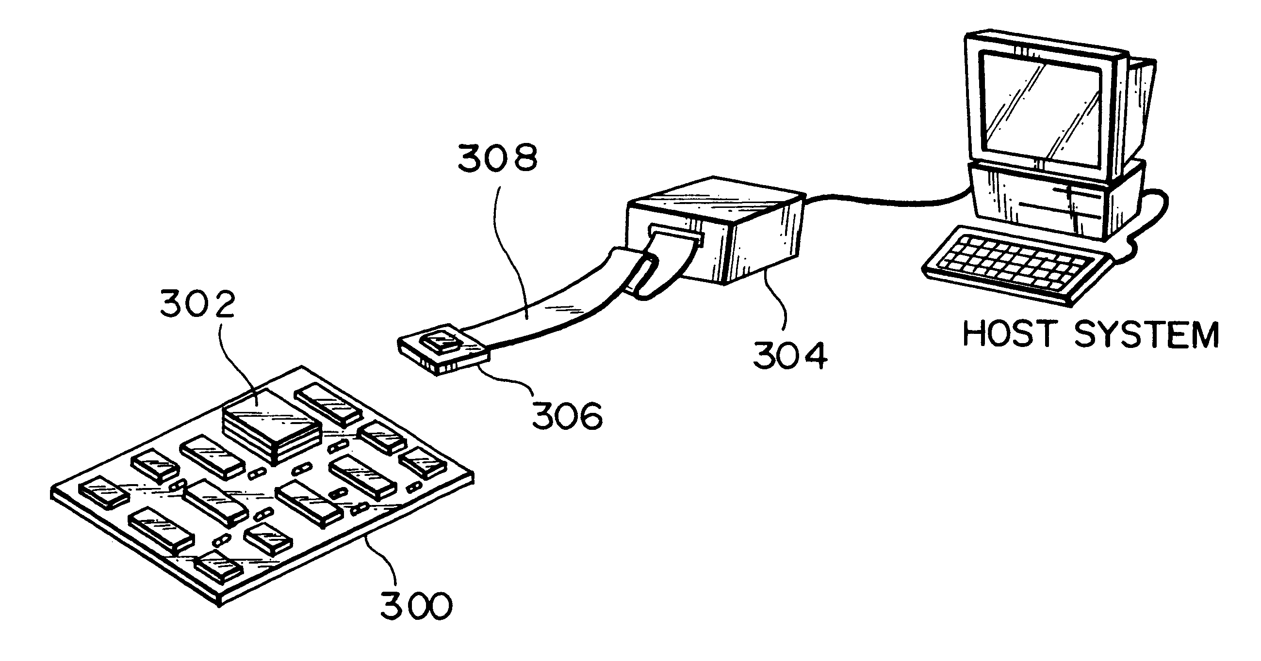
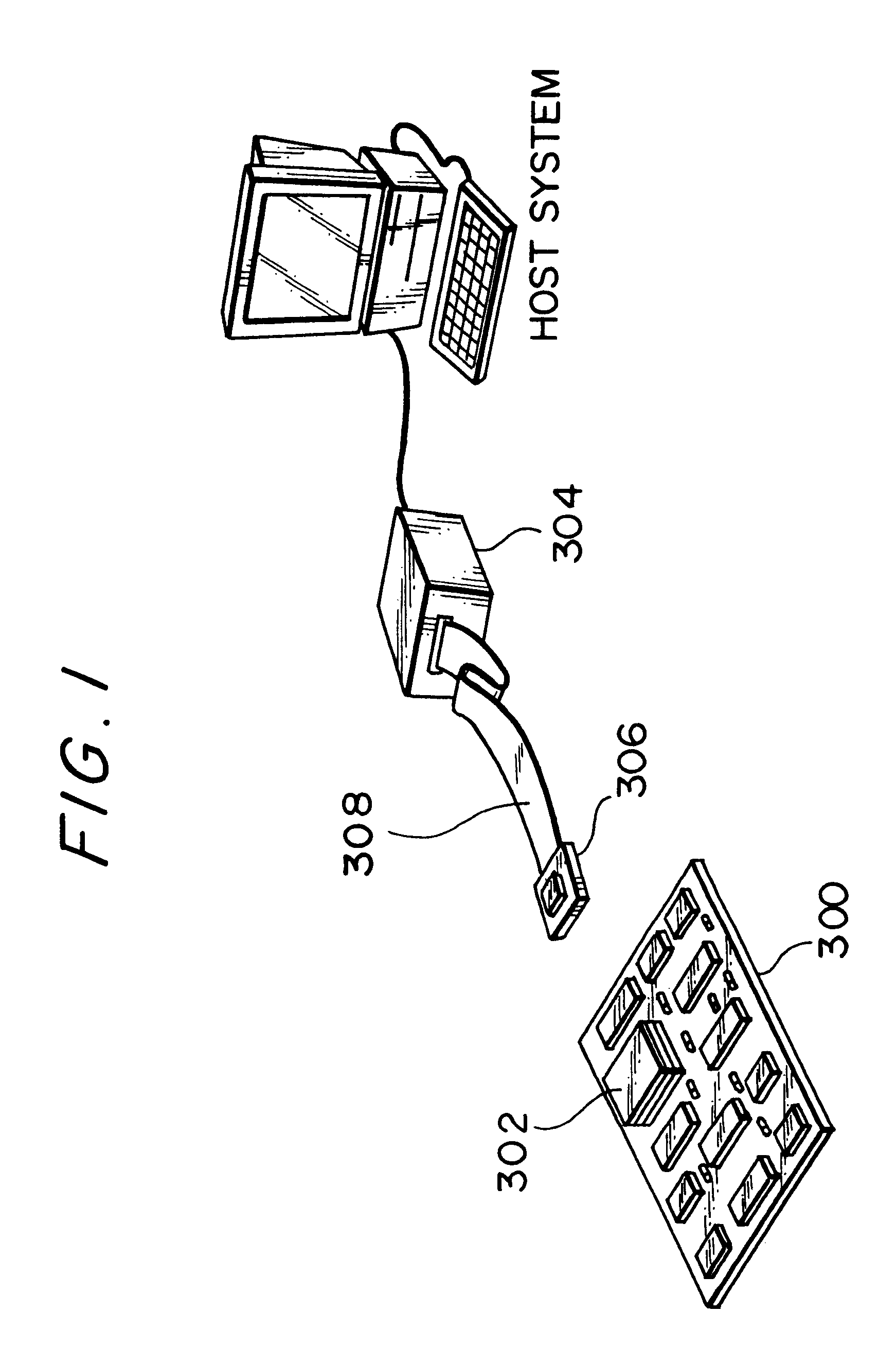
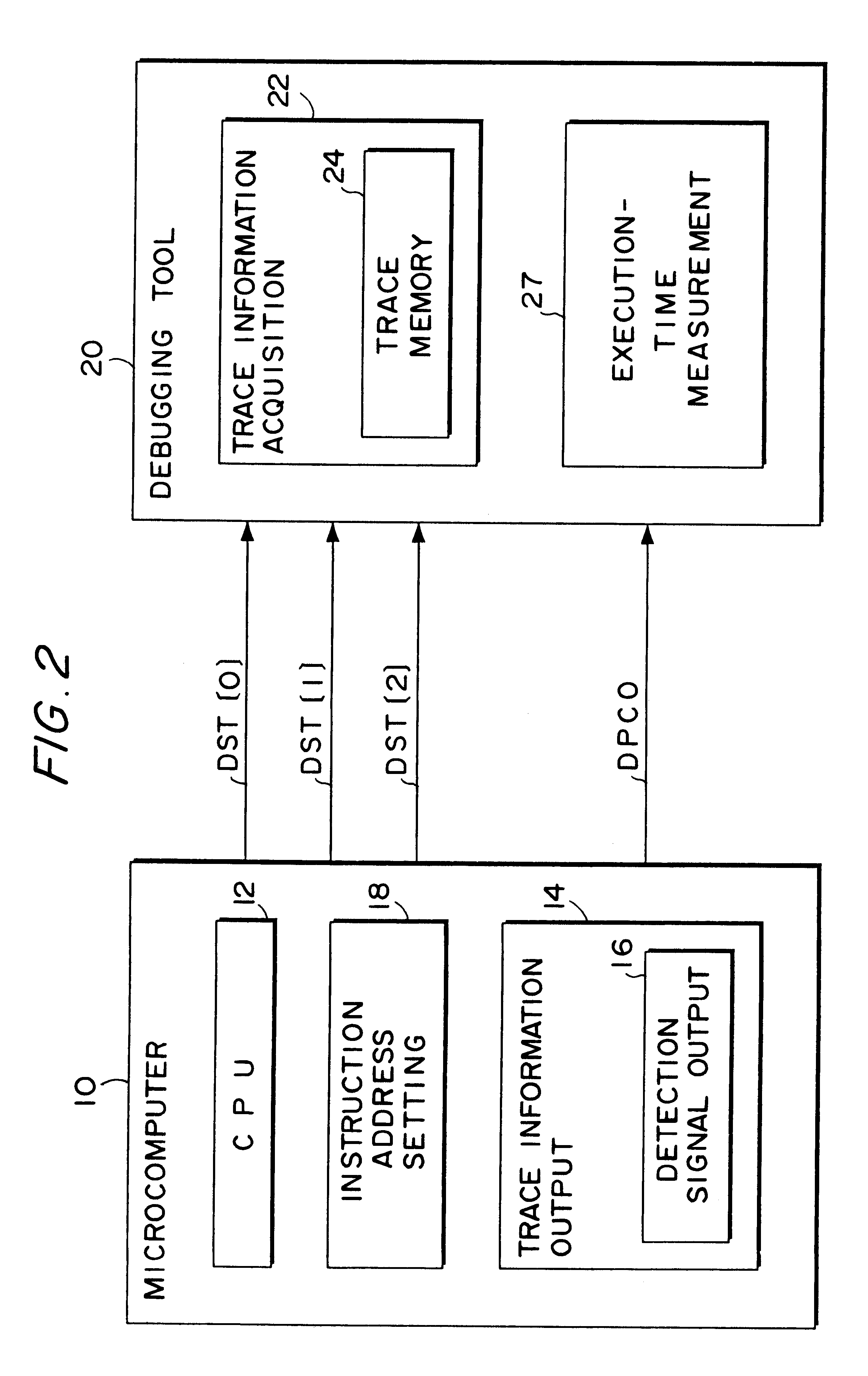
detailed example of the structure of the microcomputer and debugging system of this embodiment is shown in FIG. 6. As shown in FIG. 6, the microcomputer 10 comprises a CPU 12, a bus control unit (BCU) 26, an internal memory 28, a clock generation section 30, an on-chip monitor section 40, and the trace information output section 14.

In this case, the CPU 12 executes various instructions and comprises internal registers 13. The internal registers 13 comprise general-purpose registers R0 to R15 as well as a stack pointer (SP) register, a higher arithmetic register (AHR) for storing sum-of-products result data, and a lower arithmetic register (ALR) for storing sum-of-products result data, which are special registers.

The BCU 26 controls buses. It controls a bus 31 of a Harvard architecture connected to the CPU 12, a bus 32 connected to the internal memory 28, an external bus 33 connected to the external memory 36, and an internal bus 34 connected to components such as the trace informati...


PUM


Abstract

The present invention provides a microcomputer that makes, it possible to implement a real-time trace on a mass-produced chip using few terminals, acquire trace information from within a specified range, and measure execution times, together with electronic equipment and a debugging system comprising this microcomputer.A trace information output section (16) outputs trace information for implementing a real-time trace, to four dedicated terminals. It outputs instruction execution status information (DST[2:0]) of the CPU to three terminals and the PC value (DPCO) of a branch destination when an PC absolute branch has occurred, serially to one terminal. A microcomputer (10) outputs information indicating the start and end of a trace range or execution-time measurement range to DST[2] in a predetermined sequence. A debugging tool (20) determines the start and end of the trace range or execution-time measurement range from the values in DST[2].

Description

The present invention relates to a microcomputer and also to electronic equipment and a debugging system comprising the same.BACKGROUND OF ARTThere has recently been increasing demand for the incorporation of microcomputers that are capable of implementing high-level information processing into electronic equipment such as game machines, car navigation systems, printers, and portable information terminals. Such a thus-incorporated microcomputer is usually mounted on a user board called a target system. A software development support tool called an in-circuit emulator (ICE) is widely used for supporting the development of software to be used in the target system.The CPU-switching type of ICE shown in FIG. 1 is the most common type of this kind of ICE used in the art. With this CPU-switching ICE, a microcomputer 302 is removed from a target system 300 during debugging, and a probe 306 of a debugging tool 304 is connected thereto instead. This debugging tool 304 emulates the operation ...

Claims


Application Information

Patent Timeline
Patent Type & Authority Patents(United States)
IPC IPC(8): G06F11/36G06F11/28G06F11/22G06F15/78
CPCG06F11/3636G06F11/3656G06F11/3648G06F2201/88
Inventor MIYAYAMA, YOSHIYUKIKUDO, MAKOTOHIJIKATA, YOICHI
Owner SEIKO EPSON CORP
Why Eureka
Try Eureka