Two-optical signal generator for generating two optical signals having adjustable optical frequency difference

a technology of optical frequency difference and optical signal, which is applied in multiplex communication, semiconductor lasers, instruments, etc., can solve the problems of deteriorating phase noise characteristic of millimeter-wave signals, inability to use optical transmitters of the first prior art, and extremely low output ra

Inactive Publication Date: 2004-01-06
PANASONIC CORP
View PDF2 Cites 60 Cited by
  • Summary
  • Abstract
  • Description
  • Claims
  • Application Information

AI Technical Summary

Problems solved by technology

However, the first prior art suffers from such a problem that the phase noise characteristic of the millimeter-wave signal deteriorates due to a limitation of frequency stabilization by using a frequency control circuit, and this leads to that the optical transmitter of the first prior art cannot be used as it is in radio communications.
Also, the second prior art suffers from such a problem that, although the millimeter-wave frequency can be changed by adjusting the modulation frequency of the sine-wave signal, the setting precision of the frequencies fluctuate with a range up to approximately 200 MHz, and then, it is extremely low.
Further, the third prior art has the distributed feedback optical filter in the laser, so suffers from a small frequency range in which the laser can oscillate, and al

Method used


Image

  • Two-optical signal generator for generating two optical signals having adjustable optical frequency difference
  • Two-optical signal generator for generating two optical signals having adjustable optical frequency difference
  • Two-optical signal generator for generating two optical signals having adjustable optical frequency difference

Examples


second preferred embodiment

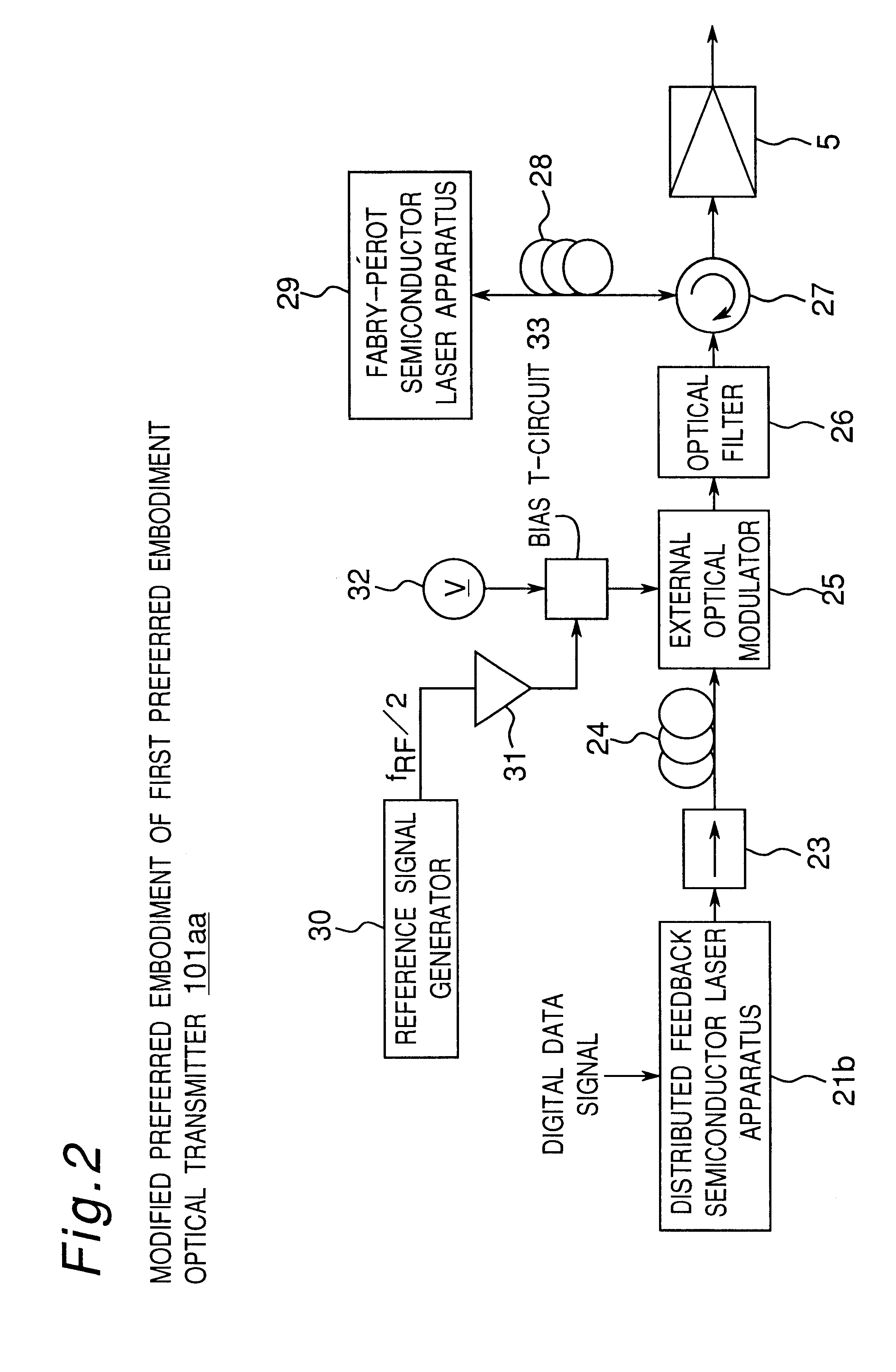
FIG. 3 is a block diagram showing a configuration of an optical transmitter 101b according to a second preferred embodiment of the present invention. The rough configuration of the optical transmitter 101b of FIG. 2 is characterized in constituting a mutual-injection locking type optical oscillation system, in which a single-mode distributed feedback semiconductor laser apparatus 21a is configured as a pass type one, an optical signal generated by distributed feedback semiconductor laser apparatus 21a is optically injected into a Fabry-Perot semiconductor laser apparatus 29, and an optical signal generated by the Fabry-Perot semiconductor laser apparatus 29 is optically injected into the distributed feedback semiconductor laser apparatus 21a.

Referring to FIG. 3, a high-frequency signal having one half of a radio frequency f.sub.RF is applied as a bias current from a reference signal generator 30 via a high-frequency amplifier 31 to the distributed feedback semiconductor laser appara...

third preferred embodiment

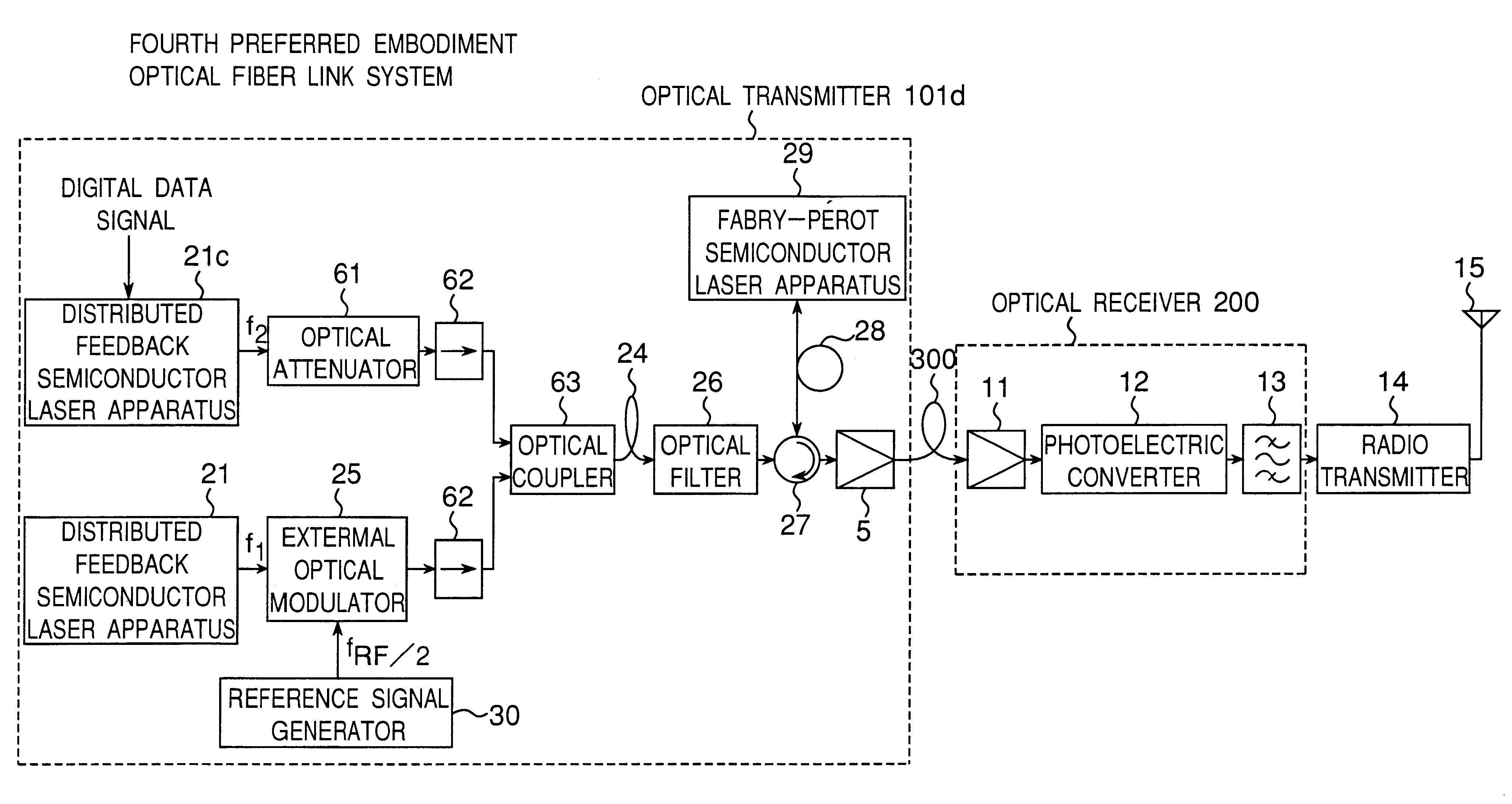
FIG. 4 is a block diagram showing a configuration of an optical fiber link system provided with an optical transmitter 101c, according to the third preferred embodiment of the present invention. The rough configuration of this optical transmitter 101c according to the third preferred embodiment is characterized in that, a single-mode optical signal generated by a distributed feedback semiconductor laser apparatus 21 are intensity-modulated by an external optical modulator 25 according to a radio signal having one half of a radio frequency f.sub.RF, the resultant intensity-modulated optical signal including two optical signals (side bands) having an optical frequency difference of the radio frequency f.sub.RF is optically injected into a Fabry-Perot semiconductor laser apparatus 29 via an optical circulator 27 and a polarization-preserving optical fiber cable 28, to injection-lock predetermined specific two optical signals of the above-mentioned optically-injected and intensity-modul...

case 1

(a) Case 1

When the digital data signal has the high level, the Fabry-Perot semiconductor laser apparatus 29 becomes such an operating or enable state that an injection current exceeds a predetermined threshold value. In this state, the predetermined specific two optical signals of the optical signals after intensity-modulation, which are optically injected via the external optical modulator 25 from the distributed feedback semiconductor laser apparatus 21, are injection-locked into the predetermined specific two optical signals of the above-mentioned multi-mode optical signals (in an ON state of injection locking), so that the Fabry-Perot semiconductor laser apparatus 29 generates the above-mentioned predetermined specific two optical signals corresponding to two modes which have simultaneously become the synchronous stable state, and then, outputs the generated predetermined specific two optical signals to an optical receiver 200 via the polarization-preserving optical fiber cable ...


PUM


Abstract

A two-optical signal generator is provided for generating two optical signals, where a difference between optical frequencies or optical wavelength of the two optical signals can be adjusted. A first optical modulator modulates a single-mode optical signal generated by a first light source according to an inputted signal, and outputs a modulated optical signal including predetermined specific two optical signals having a predetermined optical frequency difference, while a second light source generates a multi-mode optical signal including predetermined two further optical signals having substantially the same wavelengths as those of the predetermined specific two optical signals of the modulated optical signal, respectively. Then an optical injection device optically injects the modulated optical signal into the second light source, and the predetermined specific two optical signals of the modulated optical signal are injection-locked into the predetermined two further optical signals of the multi-mode optical signal, so that the second light source generates an injection-locked predetermined specific two optical signals.

Description

1. Field of the InventionThe present invention relates to a two-optical signal generator for use in an optical fiber link system or the like, and in particular, to two-optical signal generator for generating two optical signals, where a difference between optical frequencies or optical wavelengths of the two optical signals can be adjusted. In the specification, the difference between the optical frequencies is referred to as an optical frequency difference hereinafter, and the difference between the optical wavelength is referred to as an optical wavelength difference hereinafter.2. Description of the Related ArtAn optical fiber link system modulates a digital data signal into an optical signal, transmits a modulated optical signal to a radio base station, performs photoelectric conversion for a received optical signal to output a radio signal, which is then power-amplified and radio-transmitted from an antenna of a radio base station.FIG. 11 is a block diagram showing a configurat...

Claims


Application Information

Patent Timeline
IPC IPC(8): H04B10/12H04J14/02G02F2/02H01S3/10H01S5/065H04B10/293H04B10/508H04B10/54H04B10/548H04B10/564H04B10/572H04B10/588
CPCH04B10/25758H04J14/02
Inventor OGUSU, MASAHIRO
Owner PANASONIC CORP
Why Eureka
Try Eureka