Polymerization catalysts

a technology of polymerization catalyst and catalyst, which is applied in the direction of physical/chemical process catalyst, group 8/9/10/18 element organic compound, chemical/physical process, etc., can solve the problems of large sensitivity, large quantity of expensive alumoxanes, and small residual catalyst in the produced polymer

Inactive Publication Date: 2004-01-13
INEOS SALES (UK) LTD
View PDF4 Cites 20 Cited by
  • Summary
  • Abstract
  • Description
  • Claims
  • Application Information

AI Technical Summary

Benefits of technology

We have now surprisingly discovered that the activity of catalysts comprising the above compounds and MAO in polymerisation of 1-olefins can be maintained or even improved by reducing the ratio of aluminium in the MAO to transition metal. Accordingly in a first aspect the invention provides a catalyst for the polymerisation of olefins comprising
The polymerisation process of the present invention provides polymers and copolymers, especially ethylene polymers, at remarkably high productivity (based on the amount of polymer or copolymer produced per unit weight of complex employed in the catalyst system). This means that relatively very small quantities of transition metal complex are consumed in commercial processes using the process of the present invention. It also means that when the polymerisation process of the present invention is operated under polymer recovery conditions that do not employ a catalyst separation step, thus leaving the catalyst, or residues thereof, in the polymer (e.g. as occurs in most commercial slurry and gas phase polymerisation processes), the amount of transition metal complex in the produced polymer can be very small.
In the slurry phase polymerisation process the solid particles of catalyst, or supported catalyst, are fed to a polymerisation zone either as dry powder or as a slurry in the polymerisation diluent. The polymerisation diluent is compatible with the polymer(s) and catalyst(s), and may be an alkane such as hexane, heptane, isobutane, or a mixture of hydrocarbons or paraffins. Preferably the particles are fed to a polymerisation zone as a suspension in the polymerisation diluent. The polymerisation zone can be, for example, an autoclave or similar reaction vessel, or a continuous loop reactor, e.g. of the type well-know in the manufacture of polyethylene by the Phillips Process. When the polymerisation process of the present invention is carried out under slurry conditions the polymerisation is preferably carried out at a temperature above 0.degree. C., most preferably above 15.degree. C. The polymerisation temperature is preferably maintained below the temperature at which the polymer commences to soften or sinter in the presence of the polymerisation diluent. If the temperature is allowed to go above the latter temperature, fouling of the reactor can occur. Adjustment of the polymerisation within these defined temperature ranges can provide a useful means of controlling the average molecular weight of the produced polymer. A further useful means of controlling the molecular weight is to conduct the polymerisation in the presence of hydrogen gas which acts as chain transfer agent. Generally, the higher the concentration of hydrogen employed, the lower the average molecular weight of the produced polymer.
Methods for operating gas phase fluidised bed processes for making polyethylene, ethylene copolymers and polypropylene are well known in the art. The process can be operated, for example, in a vertical cylindrical reactor equipped with a perforated distribution plate to support the bed and to distribute the incoming fluidising gas stream through the bed. The fluidising gas circulating through the bed serves to remove the heat of polymerisation from the bed and to supply monomer for polymerisation in the bed. Thus the fluidising gas generally comprises the monomer(s) normally together with some inert gas (eg. nitrogen or inert hydrocarbons such as methane, ethane, propane, butane, pentane or hexane) and optionally with hydrogen as molecular weight modifier. The hot fluidising gas emerging from the top of the bed is led optionally through a velocity reduction zone (this can be a cylindrical portion of the reactor having a wider diameter) and, if desired, a cyclone and or filters to disentrain fine solid particles from the gas stream. The hot gas is then led to a heat exchanger to remove at least part of the heat of polymerisation. Catalyst is preferably fed continuously or at regular intervals to the bed. At start up of the process, the bed comprises fluidisable polymer which is preferably similar to the target polymer. Polymer is produced continuously within the bed by the polymerisation of the monomer(s). Preferably means are provided to discharge polymer from the bed continuously or at regular intervals to maintain the fluidised bed at the desired height. The process is generally operated at relatively low pressure, for example, at 10 to 50 bars, and at temperatures for example, between 50 and 120.degree. C. The temperature of the bed is maintained below the sintering temperature of the fluidised polymer to avoid problems of agglomeration.

Problems solved by technology

The quantities of residual catalyst remaining in the produced polymer are so small as to render unnecessary their separation and removal for most commercial applications.
However, metallocene catalysts of this type suffer from a number of disadvantages, for example, high sensitivity to impurities when used with commercially available monomers, diluents and process gas streams, the need to use large quantities of expensive alumoxanes to achieve high activity, and difficulties in putting the catalyst on to a suitable support.

Method used


Image

  • Polymerization catalysts
  • Polymerization catalysts
  • Polymerization catalysts

Examples


example 1a

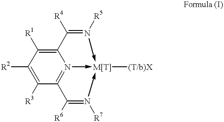
Preparation of 2,6-diacetylpyridine bis (2,4,6-trimethylphenyl amine) FeCl.sub.2 Complex

4 g of 2,6-diacetylpyridine, 10.32 ml of 2,4,6-trimethylaniline and 0.1 g of p-toluenesulphonic acid monohydrate were added to 300 ml of dry toluene in a 500 ml round bottomed flask. A 20 ml Dean-Stark heavy fractionating column and condenser were attached and the mixture heated with stirring to 160.degree. C. The reaction appeared to have gone to completion in about 3 hours. The solution was then evacuated and 200 ml of methanol added. 2,6-diacetylpyridine bis (2,4,6-trimethylphenyl amine) precipitated out and was isolated by filtration and washed with 3 aliquots of 20 ml of methanol.

3.19 g of iron(II) chloride were weighed into a half liter Schlenk tube and 400 ml of n-butanol added. The suspension was warmed to 90.degree. C. and stirred for 3 hours. 10 g of 2,6-diacetylpyridine bis (2,4,6-trimethylphenyl amine) was added as a solid at 80.degree. C. The reaction was stirred for 1 hour then at 2...

example 1b

Preparation of the Catalyst

The equipment used for calcining the silica support was composed essentially of a vertical quartz cylinder, 75 cm high and 5 cm in diameter, above which was placed a disengagement zone. This calcinator was equipped with a fluidisation grid made from porous quartz and positioned in the lower part of the quartz cylinder. It was also equipped with an electrical resistance heater and a supply of fluidising nitrogen.

Into the calcinator maintained at 60.degree. C. and supplied with nitrogen containing less than 2 vpm of water vapour and with a flow rate of 4.7 ml / s, were charged 30 g of silica sold under the trade name of ES70X by Crosfield Catalysts (Warrington, England). Next the calcinator was heated from 60 to 600.degree. C. at a rate of 100.degree. C. / h. The silica was then maintained at 600.degree. C. for 16 hours in the fluidised state. The silica was then cooled to 25.degree. C. and stored under dry nitrogen.

All subsequent operations were carried out in ...

example 1c

Ethylene Polymerisation in the Gas Phase

400 g of polyethylene pellets were introduced into a stainless steel reactor of capacity 2.6 liters equipped with a stirrer and maintained under a nitrogen atmosphere. The reactor was heated to 100.degree. C., stirred at 50 rpm and 0.7 g of silica previously treated with 1.5 mmole / g of triethylaluminium was added as poison scavenger. Next 0.1025 g of the above catalyst (see 1b) was added. Then hydrogen was introduced to pressure the reactor to 0.1 MPa. Finally ethylene was fed until a total pressure of 0.8 MPa was obtained. Ethylene was fed to maintain this pressure throughout the reaction. After production corresponding to 50 g polyethylene per gram of catalyst, the stirring rate was increased to 100 rpm, after the production of 50 g of polyethylene the stirring rate was increased further to 150 rpm and after the production of 100 g of polyethylene the stirring rate was increased further to 200 rpm.

Polymerisation was allowed to continue for 1...


PUM

PropertyMeasurementUnit
temperaturesaaaaaaaaaa
pressureaaaaaaaaaa
temperatureaaaaaaaaaa

Abstract

The present invention relates to a process for the polymerization and copolymerization of 1-olefins and to a catalyst to be used in said process wherein the catalyst comprises (1) a complex having formula (I) wherein M is Fe[II], Fe[III], Co[I], Co[II], Co[III], Mn[I], Mn[II], Mn[III], Mn[IV], Ru[II], Ru[III] or Ru[IV]; X represents an atom or group covalently or ionically bonded to the metal M; T is the oxidation state of the metal; b is the valency of the atom or group X; and R 1 to R 7 are each independently selected from hydrogen, halogen, hydrocarbyl, substituted hydrocarbyl, heterohydrocarbyl, substituted heterohydrocarbyl or SiR' 3 where each R' is independently selected from hydrogen, halogen, hydrocarbyl, substituted hydrocarbyl, heterohydrocarbyl, substituted heterohydrocarbyl; and when any two or more of R 1 to R 7 are hydrocarbyl, substituted hydrocarbyl, heterohydrocarbyl or substituted heterohydrocarbyl, said two or more can be linked to form one or more cyclic substituents; (2) an activator which is an alkylalumoxane; and (3) a support material, wherein the atomic ratio of aluminium in the alkylalumoxane (2) to transition metal M in (1) is from 6:1 to 25:1.

Description

The present invention relates to transition metal compounds and to polymerisation catalyst systems employing them.The use of certain transition metal compounds to polymerise 1-olefins, for example, ethylene, is well established in the prior art. The use of Ziegler-Natta catalysts, for example, those catalysts produced by activating titanium halides with organometallic compounds such as triethylaluminium, is fundamental to many commercial processes for manufacturing polyolefins. Over the last twenty or thirty years, advances in the technology have led to the development of Ziegler-Natta catalysts which have such high activities that that olefin polymers and copolymers containing very low concentrations of residual catalyst can be produced directly in commercial polymerisation processes. The quantities of residual catalyst remaining in the produced polymer are so small as to render unnecessary their separation and removal for most commercial applications. Such processes can be operate...

Claims


Application Information

Patent Timeline
Patent Type & Authority Patents(United States)
IPC IPC(8): C08F110/02C08F110/00C08F4/70C08F10/00C08F4/60
CPCC08F10/00C08F110/02C08F4/695C08F4/025C08F4/7042C08F2500/12C08F2500/07Y10S526/901Y10S526/905
Inventor BERARDI, ALAINSPEAKMAN, JOHN GABRIEL
Owner INEOS SALES (UK) LTD
Why Eureka
Try Eureka