
Magnetoelastic sensor for characterizing properties of thin-film/coatings

a thin film/coating and magnetic sensor technology, applied in the field of telemetry techniques, can solve the problems of requiring several hours for result generation and prolonged testing regime, and achieve the effects of reducing trouble, reducing measurement time, and reducing measurement tim

Inactive Publication Date: 2004-02-10
UNIV OF KENTUCKY RES FOUND
View PDF36 Cites 38 Cited by
  • Summary
  • Abstract
  • Description
  • Claims
  • Application Information

AI Technical Summary

Benefits of technology

The invention is a compact apparatus and method for measuring and monitoring the elasticity characteristics of a thin-film layer on a base magnetostrictive element. The apparatus can be used for one-time disposable operation or continuous monitoring of the thin-film layer as it reacts to various agents. It can be used in various biomedical applications, manufacturing processes, and material science research tools. The apparatus is easy to use, requires no hard-wire connection, and can provide results quickly. It can also be incorporated into self-diagnostic kits for real-time monitoring of blood coagulation. The thin-film layer can be shaped or applied in a way that optimizes its response to external agents, and multiple sensor elements can be used to provide more information about the elasticity characteristics of the thin-film layer. The design of the apparatus is simple and economically feasible.

Problems solved by technology

Present monitoring practices require the removal of relatively large blood samples (2-10 ml) and extensive sample preparation prior to titration analysis resulting in a prolonged testing regime, which can require several hours for result generation.

Method used


Image

  • Magnetoelastic sensor for characterizing properties of thin-film/coatings
  • Magnetoelastic sensor for characterizing properties of thin-film/coatings
  • Magnetoelastic sensor for characterizing properties of thin-film/coatings

Examples


Embodiment Construction

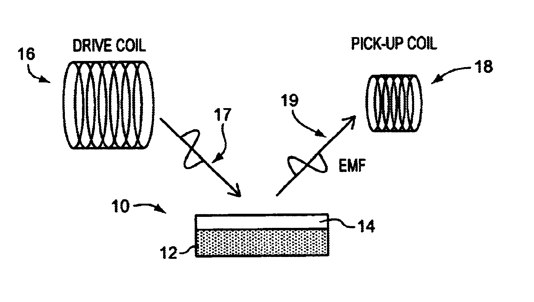
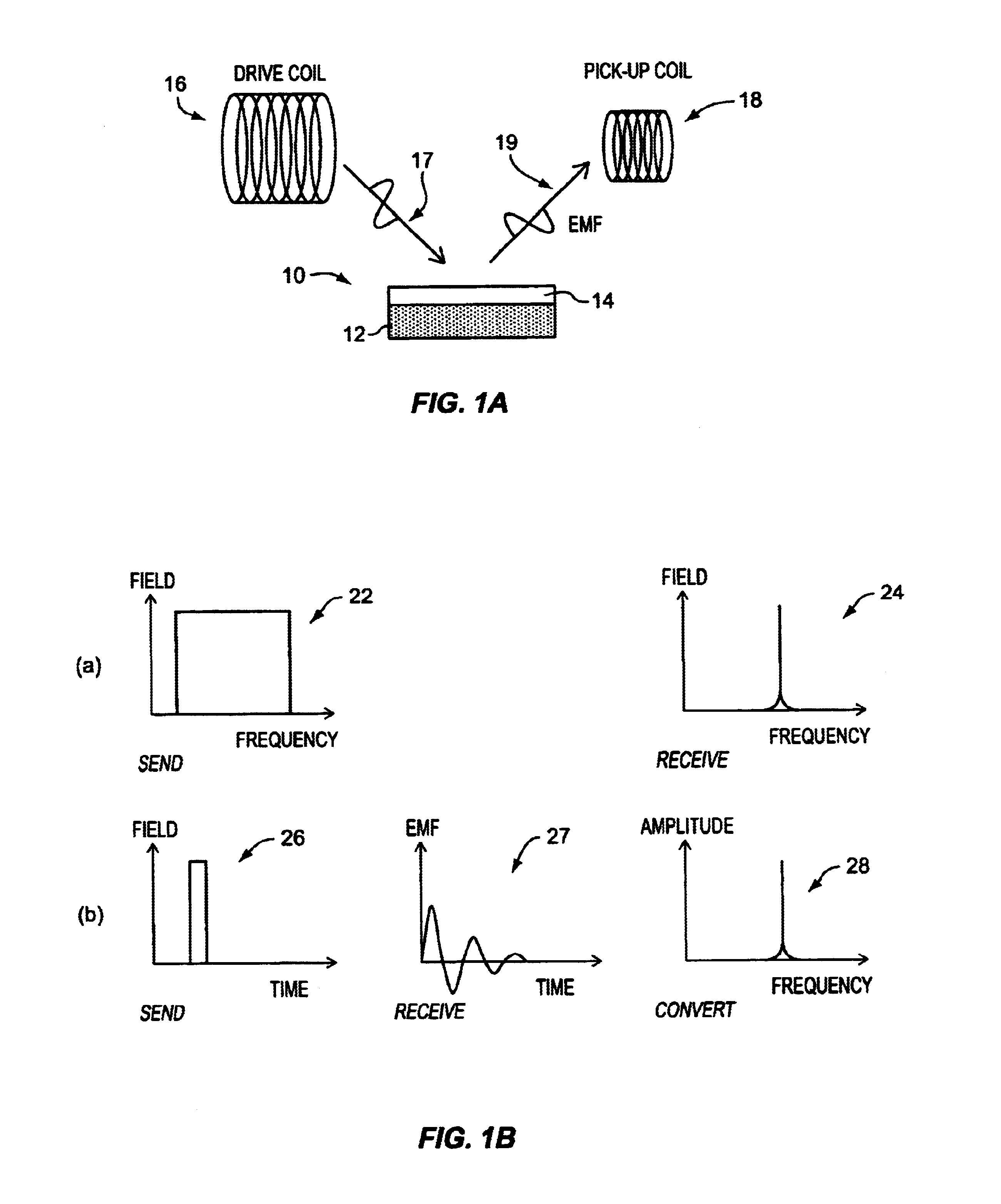
FIG. 1A schematically depicts components of an apparatus and method of the invention for remote query of a thin-film layer or coating 14 atop a base magnetostrictive element 12. A time-varying magnetic field 17 is applied to sensor element 10, with a layer / coating 14 of interest having been deposited onto a surface of the base 14, by way of a suitable drive coil 16 such that emissions 19 from the sensor element can be picked-up by a suitable pick-up coil 18. Two useful ways to measure the frequency spectrum include: frequency domain measurement and the time domain measurement. In the frequency domain measurement, the sensing element's vibration is excited by an alternating magnetic field of a monochromatic frequency. The amplitude of the sensor response is then registered while sweeping (`listening`) over a range of frequencies that includes the resonance frequency of the sensor element. Finding the maximum amplitude of the sensor response leads to the characteristic resonant freque...


PUM

PropertyMeasurementUnit
acoustic resonant frequencyaaaaaaaaaa
frequencyaaaaaaaaaa
frequenciesaaaaaaaaaa

Abstract

An apparatus for determining elasticity characteristics of a thin-film layer. The apparatus comprises a sensor element having a base magnetostrictive element at least one surface of which is at least partially coated with the thin-film layer. The thin-film layer may be of a variety of materials (having a synthetic and / or bio-component) in a state or form capable of being deposited, manually or otherwise, on the base element surface, such as by way of eye-dropper, melting, dripping, brushing, sputtering, spraying, etching, evaporation, dip-coating, laminating, etc. Among suitable thin-film layers for the sensor element of the invention are fluent bio-substances, thin-film deposits used in manufacturing processes, polymeric coatings, paint, an adhesive, and so on. A receiver, preferably remotely located, is used to measure a plurality of values for magneto-elastic emission intensity of the sensor element in either characterization: (a) the measure of the plurality of values is used to identify a magneto-elastic resonant frequency value for the sensor element; and (b) the measure of the plurality of successive values is done at a preselected magneto-elastic frequency.

Description

BACKGROUND OF THE INVENTIONPENDING APPLICATIONS FOR MAGNETOELASTIC SENSORS FILED BY ASSIGNEEOn Dec. 30, 1998, the assignee hereof filed a U.S. nonprovisional patent application for an applicant hereof, Dr. Craig Grimes, currently pending as Ser. No. 09 / 223,689 entitled "Remote Magneto-elastic Analyte, Viscosity and Temperature Sensing Apparatus and Associated Methods of Sensing". On Feb. 11, 2000 the assignee hereof filed a U.S. nonprovisional patent application for applicants hereof, Dr. Craig Grimes and Dr. Dimitris Kouzoudis, currently pending as Ser. No. 09 / 502,663 entitled "Magnetoelastic Sensing Apparatus and Method for Remote Pressure Query of an Environment."FIELD OF THE INVENTIONIn general, the present invention relates to telemetry techniques for direct measurement of, as well as measuring changes in, material characteristics such as mass, thickness, density, and elasticity. More particularly, the invention is directed to a new apparatus and method for remotely measuring o...

Claims


Application Information

Patent Timeline
Patent Type & Authority Patents(United States)
IPC IPC(8): G01N33/49G01N11/10G01N11/16G01N9/00
CPCG01N33/4905G01N9/002G01N11/16
Inventor BACHAS, LEONIDAS G.BARRETT, GARYGRIMES, CRAIG A.KOUZOUDIS, DIMITRISSCHMIDT, STEFAN
Owner UNIV OF KENTUCKY RES FOUND
Learn More