
Apparatus for microchip laser geo-sensors

a laser geosensor and microchip technology, applied in the field of laser sensors, can solve the problems of high system cost, military applications have the luxury of demanding the highest performance with concomitant high system cost, and the cost and sensitivity of such systems may preclude their ability to displace the highly cost-effective linear induction sensor used today, and the specifications represent a formidable challenge for optical sensors

Inactive Publication Date: 2004-02-17
WESTERNGECO LLC
View PDF16 Cites 21 Cited by
  • Summary
  • Abstract
  • Description
  • Claims
  • Application Information

AI Technical Summary

Problems solved by technology

Military applications, however, have the luxury of demanding the highest performance with concomitant high system costs.
While several companies are exploring the use of optical fiber sensor technologies such as Bragg gratings for down-hole oil and gas sensor applications, the cost and sensitivity of such systems may preclude their ability to displace the highly cost-effective linear induction sensors used today.
These specifications represent a formidable challenge for optical sensors.
Based on these requirements, optical sensor designers have avoided using active optical devices at the sensor pod, due among other things to the challenging design problems presented when temperature cycling the sensor pod.
This is a disadvantage of intensity modulated designs.
In practice, common mode phase and amplitude modulation is difficult to achieve, and as a result a high common mode rejection at the receiver electronics is difficult to achieve.

Method used


Image

  • Apparatus for microchip laser geo-sensors
  • Apparatus for microchip laser geo-sensors

Examples


Embodiment Construction

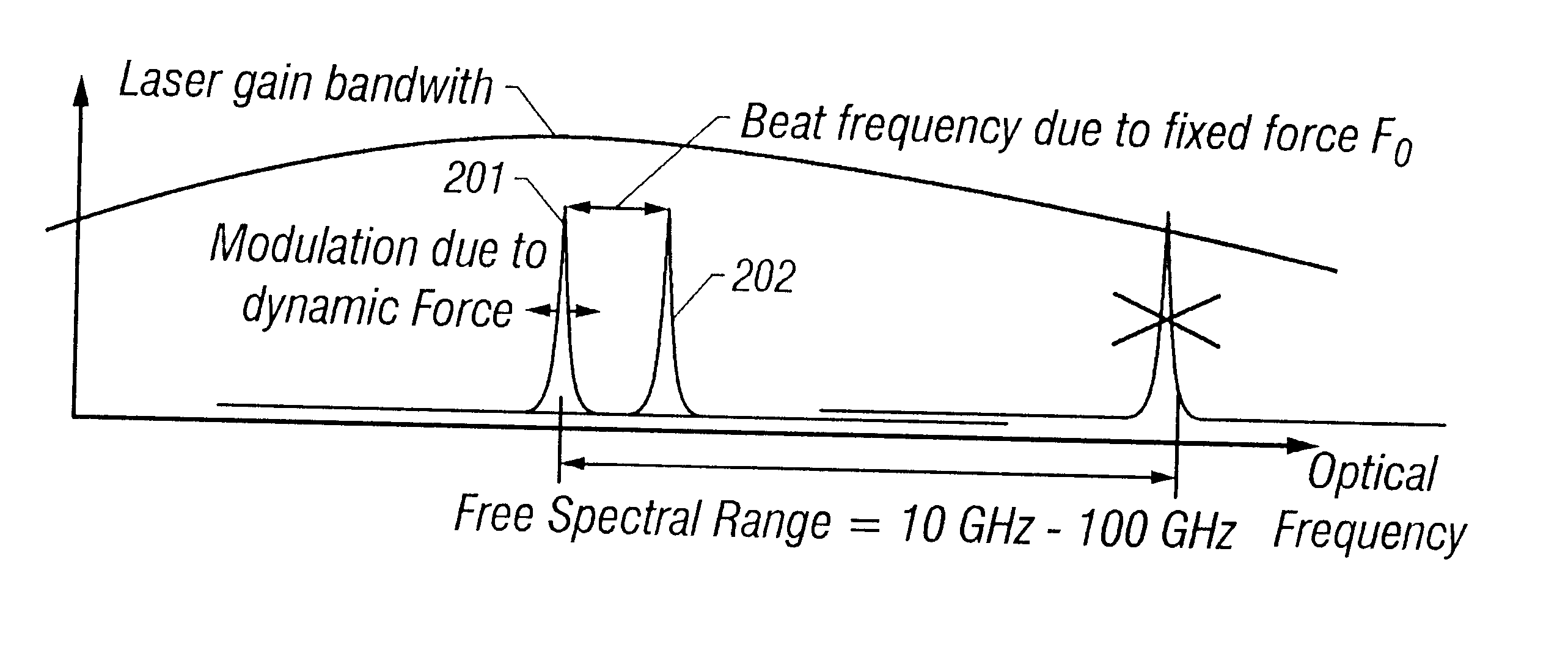
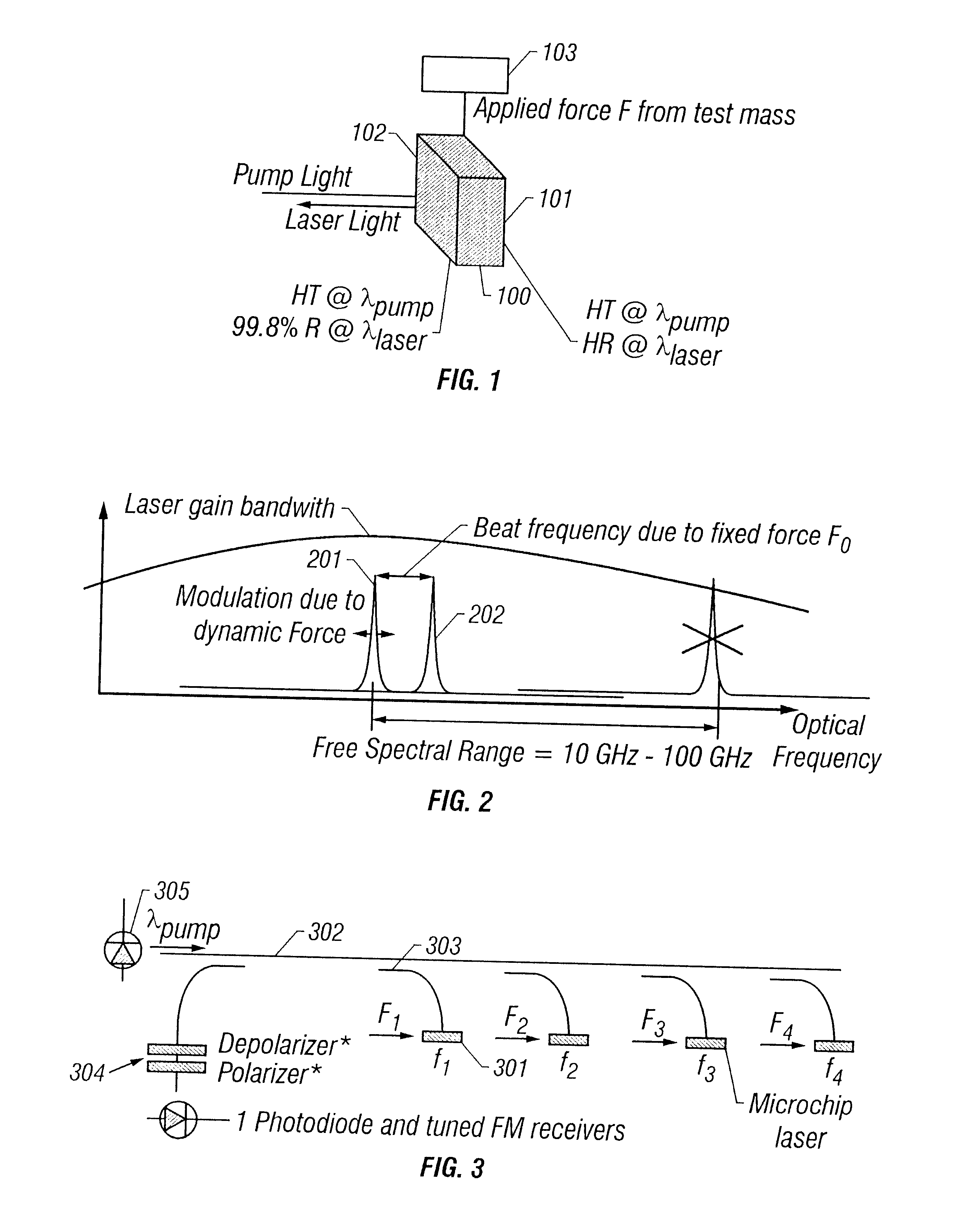
The present invention provides an active optical element in a sensor pod, which provides significant common mode noise immunity through the use of a self heterodyning FM modulation technique. The apparatus of the present invention provides a microchip laser as a sensing element. A microchip laser, shown in FIG. 1, consists of a solid monolith of single crystal lasing material 100 such as Nd:YAG (Neodymium doped Yttrium Aluminum Garnet) polished to precise tolerances on two opposing faces. A first face 102 is coated with a dielectric mirror which provides 99%-99.9% reflectance at the lasing wavelength (1064 nm for the case of Nd:YAG), and passes almost all of the optical pump wavelength used to excite the laser (for Nd:YAG, this is at 808 mu). A second face 101 is coated with a high reflector at both the pump wavelength and the lasing wavelength. When an optical beam at 808 nm is focused down to a 50-100 .mu.m diameter spot in the crystal, the Nd ions absorb this energy and fluoresce...


PUM


Abstract

An optical geophone or hydrophone for detecting seismic vibrational energy comprising a laser material, which generates a lasing frequency signal, the frequency of which varies in accordance with vibrational energy incident upon the laser material, a light source occurring at an excitation frequency for providing excitation energy incident upon the laser material, so that the laser material emits light at the lasing frequency modulated by the vibrational energy and a fiber optic cable for transmitting the excitation frequency light to the laser material and receiving the frequency modulated lasing frequency for transmission to a receiver. The laser material comprises a first face and a second face, the first face being parallel to the second face. The first face is coated so that it passes substantially all of the lasing frequency light and reflects substantially all of the excitation frequency light. The second face is coated so that the second face reflects substantially all of the lasing frequency light and substantially all of the excitation frequency light. An acoustic amplifier is provided for coupling vibrational energy to the laser material, wherein the vibrational energy is incident upon a side of the laser material orthogonal or parallel to the incidence of the excitation energy.

Description

1. Field of the InventionThis invention relates to laser sensors for measuring faint vibrations or pressure waves at low frequencies on land or at sea.2. Related ArtMicrochip lasers have been used in vibration detection in ultrasound U.S. Pat. No. 5,353,262 entitl ed "Optical Transducer and Method of Use" by Yakymyshyn, et al. discloses an optical transducer, for an ultrasound system, which includes a signal laser that generates an optical signal the frequency of which varies in correspondence with acoustic energy incident on the transducer. An optical cavity in the signal laser is disposed such that incident acoustic energy causes compression and rarefaction of the optical cavity, and this displacement varies the optical frequency generated by the laser. A laser pump coupled to the lasing medium is adapted to apply selected levels of excitation energy appropriate to the generation and detection of acoustic pulses. The signal laser alternatively is adapted such that the refractive i...

Claims


Application Information

Patent Timeline
IPC IPC(8): G01H9/00G01V1/18G01V1/16
CPCG01H9/00G01V1/181
Inventor AMBS, LORANYAKYMYSHYN, CHRIS
Owner WESTERNGECO LLC
Learn More