
Robust process identification and auto-tuning control

a process identification and auto-tuning control technology, applied in the field of system identification and control design, can solve the problems of insufficient description of non-minimum phase systems in the sopdt model, inability to robustly noise-reducing graphical methods, and inability to identify plant models in closed-loop operation

Inactive Publication Date: 2004-02-24
NAT UNIV OF SINGAPORE
View PDF4 Cites 86 Cited by
  • Summary
  • Abstract
  • Description
  • Claims
  • Application Information

AI Technical Summary

Benefits of technology

The present invention provides improved identification and control methods for single and multi-variable plants using advanced techniques such as modeling and control design. The invention addresses the challenges of accurately identifying and controlling processes with delay, which is present in most industrial processes. The invention provides a unified framework for identifying and controlling multivariable systems and can work with a wide range of experimental tests. The invention also addresses the difficulty of tuning PID controllers and the need for advanced control strategies for general processes. Overall, the invention enhances control performance and management of industrial processes.

Problems solved by technology

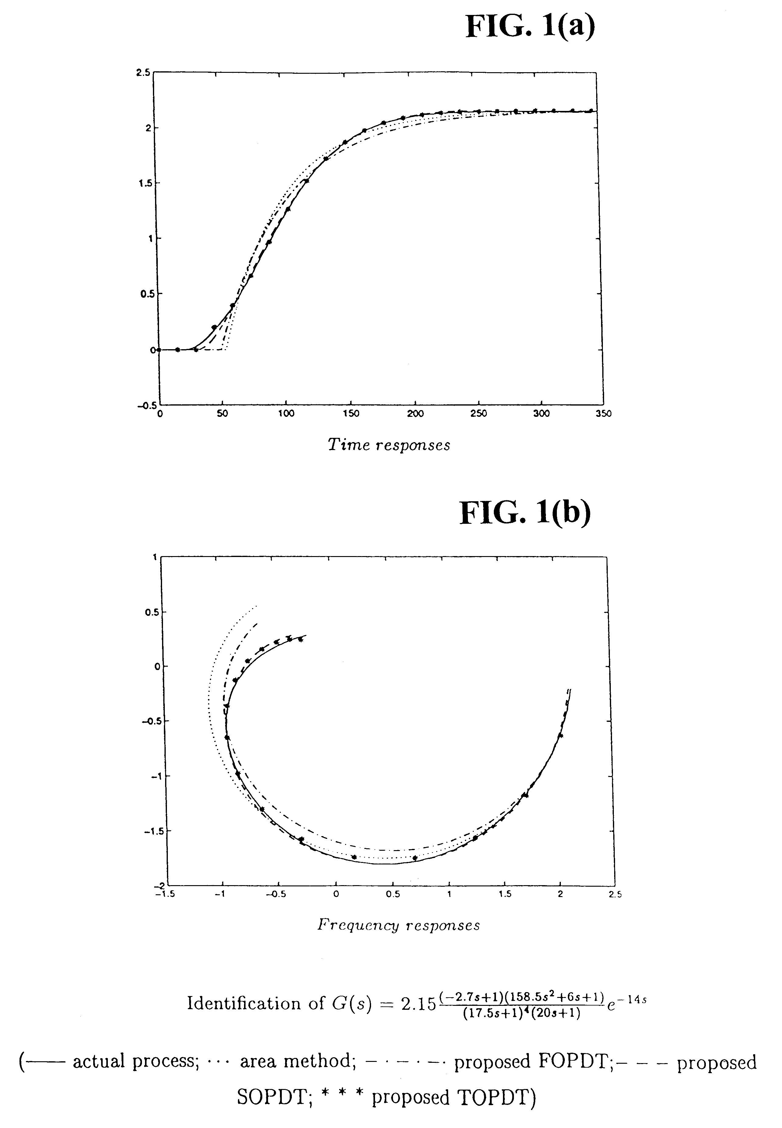
Though there are many methods available for system identification from a step test (Strejc 1980), most of them do not consider the process delay (or dead-time) or just assume knowledge of the delay.
Yet, there are certainly many other processes for which the model (1) is not adequate to describe the dynamics, or for which higher-order modeling could improve accuracy significantly.
However, such a SOPDT model does not adequately describe non-minimum-phase systems.
Further, though model parameters can be easily calculated using several points from the system response, such graphical methods may not be robust to noise.
Further, though most tests can be done in open-loop, the plant model identification in closed-loop operation is also an important practical issue.
In some cases the plant can be operated in open-loop with difficulties or a control may already exist and it is not possible to open the loop.
However, most existing closed-loop identification methods suffer from one or more of the following inherent drawbacks: not robust to measurement noise; an FOPDT model can only be reconstructed; and / or the controller is restricted to the proportional type.
(i) Due to the adoption of describing function approximation, the estimation of the critical point is not accurate in nature.
These methods are time consuming and the resulting estimation is still approximate in nature since they actually make repeated use of the standard method.
Interactions usually exist between control loops, and this causes the renowned difficulty in their identification and control compared with single-input single-output (SISO) processes.
However, no process model is generated from the procedures.
However, despite the fact that the use of PID control is well established in process industries, many control loops are still found to perform poorly.
In spite of the enormous amount of research work reported in the literature, tuning a good PID controller is still recognized as a rather difficult task.
They will rapidly lose their effectiveness when the process deadtime is much larger than the process time constant.
In spite of the effectiveness of the control scheme, the internal model control has disadvantages that hindered its wider use in industry.
In cases with large modeling errors, its performance will not be satisfactory.
The goal of controller design to achieve satisfactory loop performance has also posed a great challenge in the area of multivariable control design.
However, theses methods are both manual and time consuming in nature.
In addition, the control performance of the closed loop system is usually not so satisfactory, especially in the case of large interaction and long dead time.
It is easy to understand that PID controllers could be inadequate when applying to very complex SISO processes.
The more frequently encountered case is that the dynamics of individual channels are still simple but as there are more output variables to be controlled, the interactions existing between these variables can give rise to very complicated equivalent loops for which PID control is difficult to handle.
More importantly, the interaction for such a process is too difficult to be compensated for by PID, leading to very bad decoupling performance and causing poor loop performance.
Thus, PID control even in multivariable form may fail.
However, serious performance degradation may be observed when the sampling frequency is low.
In real life, the sampling frequency of a digital system is often limited by a microprocessor bandwidth, costs, etc.
The resultant performance of a low sampling frequency digital system may not be guaranteed if the conventional conversion methods are used (Rafee et al.
Besides, when a system contains delay, then the conversion will be quite complex using classical methods.
Though some special approaches to the solution have been developed recently, the algorithms proposed by the related art are either too complicated or are state-space based, which are only applicable for delay-free cases.
One crucial obstacle to the application of a disturbance observer to process control is the process time-delay (or dead-time) which exists in most industrial processes.
In practice, the true process output y may be corrupted by measurement noise .upsilon.
Choice of N The computational effort becomes heavy if too many samples are taken into consideration, which leads to the large size of .PHI.. Moreover, .PHI..sup.T.PHI. or Z.sup.T.PHI. may tend to become ill-conditioned for very large N and this may cause the computational difficulty in estimating .theta.. Therefore, N has to be limited.

Method used


Image

  • Robust process identification and auto-tuning control
  • Robust process identification and auto-tuning control
  • Robust process identification and auto-tuning control

Examples


case 1

oop (sequential) step test;

Case 2: Closed-loop (sequential) step test;

case 3

oop (sequential) relay test;

Case 4: Closed-loop (sequential) relay test. (55)

It should be stressed that the identification method to be presented below is not restricted to these four cases only, but also applicable to other cases provided that each test leads to a steady state.

To unify the presentation for all the cases, we introduce a vector .upsilon.(t): ##EQU100##

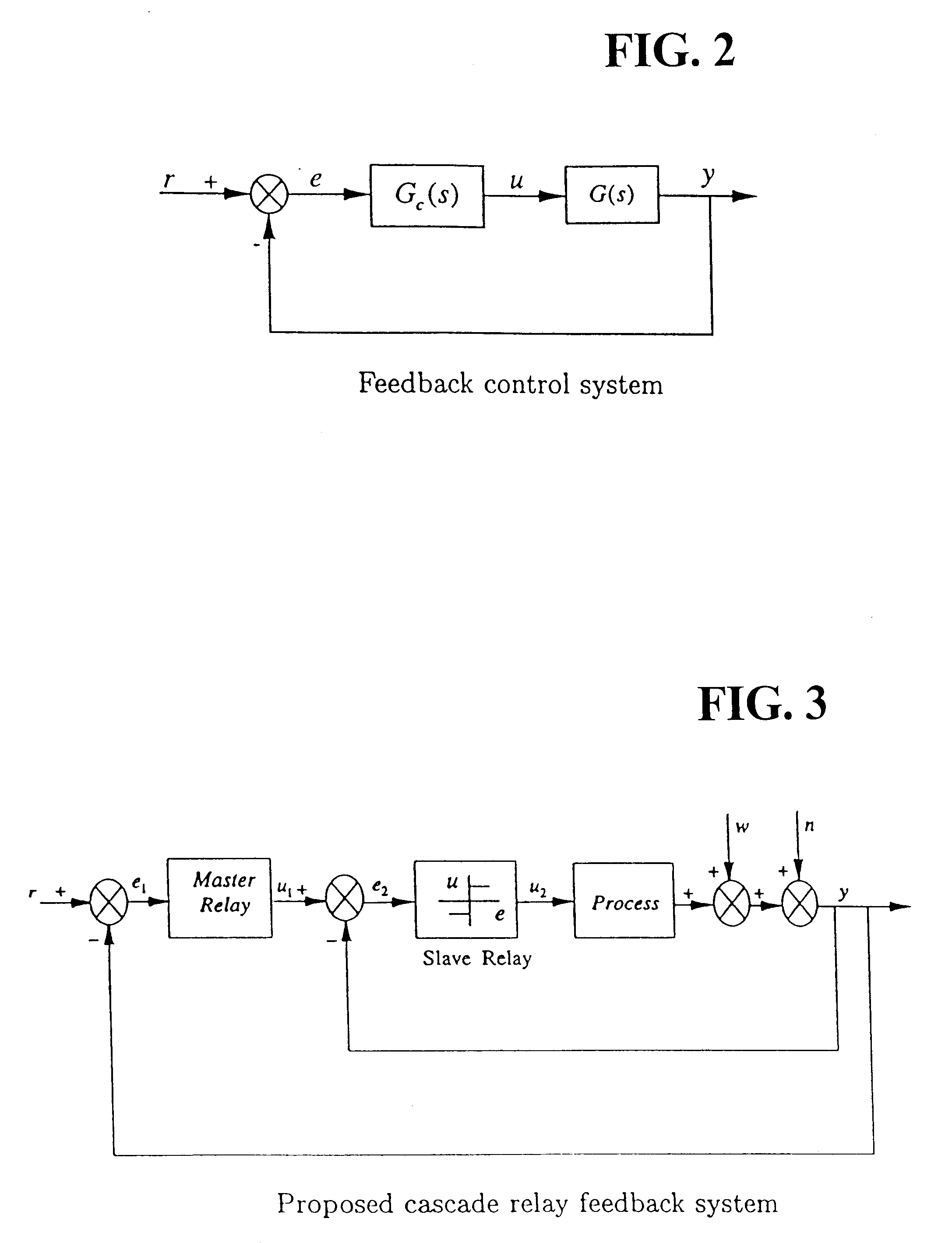
where u(t) is the input to plant and r(t) the set-point to the closed-loop of FIG. 2. Let 1(t) and .gamma.(t) be the step function with unity size and the relay function with unity magnitude, respectively. The types of test signal are reflected by the elements of .upsilon.(t): ##EQU101##

where .alpha..sub.i and .beta..sub.i are the size and amplitude of the step and relay, respectively. Then the m tests .upsilon..sup.i in a sequential experiment over the time span of [t.sub.0, t.sub.m ] with test periods, [t.sub.i-1, t.sub.i ], i=1,2, . . . , m, can be expressed as ##EQU102##

where e.sub.i is the i-th column of the m.time...

example

Consider a first-order plus dead-time process ##EQU193##

The PI controller design method proposed in Zhuang and Atherton (1993) is applied to give ##EQU194##

For the scheme in FIG. 27, suppose G(s)=G(s). In V(s), take .tau..sub..upsilon. =0.4L=2, calculate from (112) the maximum value of K.sub..upsilon. as K.sub..upsilon..sub..sub.max =1.38, then set K.sub..upsilon. =K.sub..upsilon..sub..sub.max 3=0.46. We have ##EQU195##

The filter Q(s) is in the form of ##EQU196##

and .tau..sub.q is chosen as 1 / 10T.sub.p =0.01. A unit step change in the set-point is made at t=0, and a step disturbance of the size 1 is introduced through ##EQU197##

to the system at t=50, the resulting responses are displayed in FIG. 30, where the solid line is from the proposed method, and the dashed line is from the normal feedback control without any disturbance compensator.

To evaluate our scheme of FIG. 29 for periodic disturbances, introduce instead the following periodic disturbance at t 50:

d(t)=sin(0.2.pi.t)+0.3si...


PUM


Abstract

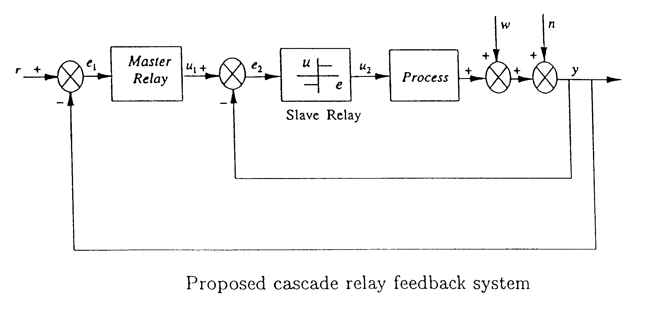
This invention provides a novel process identification and control package for high performance. For process identification, a simple yet effective and robust identification method is presented using process step responses to give a continuous transfer function with time-delay without iteration. A new relay, called cascade relay, is devised to get more accurate and reliable points on the process frequency response. For controller tuning, the internal model principle is employed to design single-loop controller PID or high-order types with best achievable control performance. The process identification and control design parts can be easily integrated into control system auto-tuning package. Further, a general control scheme for disturbance rejection is given which can significantly improve disturbance rejection performance over conventional feedback systems with time delays. Practical issues such as noises, real-time implementation and tuning guidelines are also provided. The invention covers both open-loop and closed-loop testing, and single and multivariable cases.

Description

1. Field of the InventionThe present invention relates to system identification and control design for single-variable and multi-variable plants. More particularly, the invented schemes permit improved identification accuracy and control performance over conventional methods. The present invention provides general, systematic, effective, and applicable methods for process identification and control for a wide range of industries, such as process and chemical plants, food processing, waste water treatment and environmental systems, oil refinery, servo and mechatronic systems, e.g. anywhere a system model is needed for analysis, prediction, filtering, optimization and management, and / or where control or better control is required for their systems2. Description of the Background ArtIdentifying an unknown system has been an active area of research in control engineering for a few decades and it has strong links to other areas of engineering including signal processing, system optimizat...

Claims


Application Information

Patent Timeline
Patent Type & Authority Patents(United States)
IPC IPC(8): G05B13/04G05B11/42G05B23/02
CPCG05B11/42G05B13/042
Inventor WANG, QING-GUOLEE, TONG-HENGZHANG, YONGZHANG, YUYANG, XUE-PING
Owner NAT UNIV OF SINGAPORE
Learn More