Continuous process for the preparation of polytrimethylene ether glycol

a technology of ether glycol and polytrimethylene, which is applied in the field of polyalkylene ether glycol, can solve the problems of high percentage of terminal unsaturation and product unsuitability for end-use applications

Inactive Publication Date: 2004-04-13
DUPONT CA +1
View PDF28 Cites 226 Cited by
  • Summary
  • Abstract
  • Description
  • Claims
  • Application Information

AI Technical Summary

Problems solved by technology
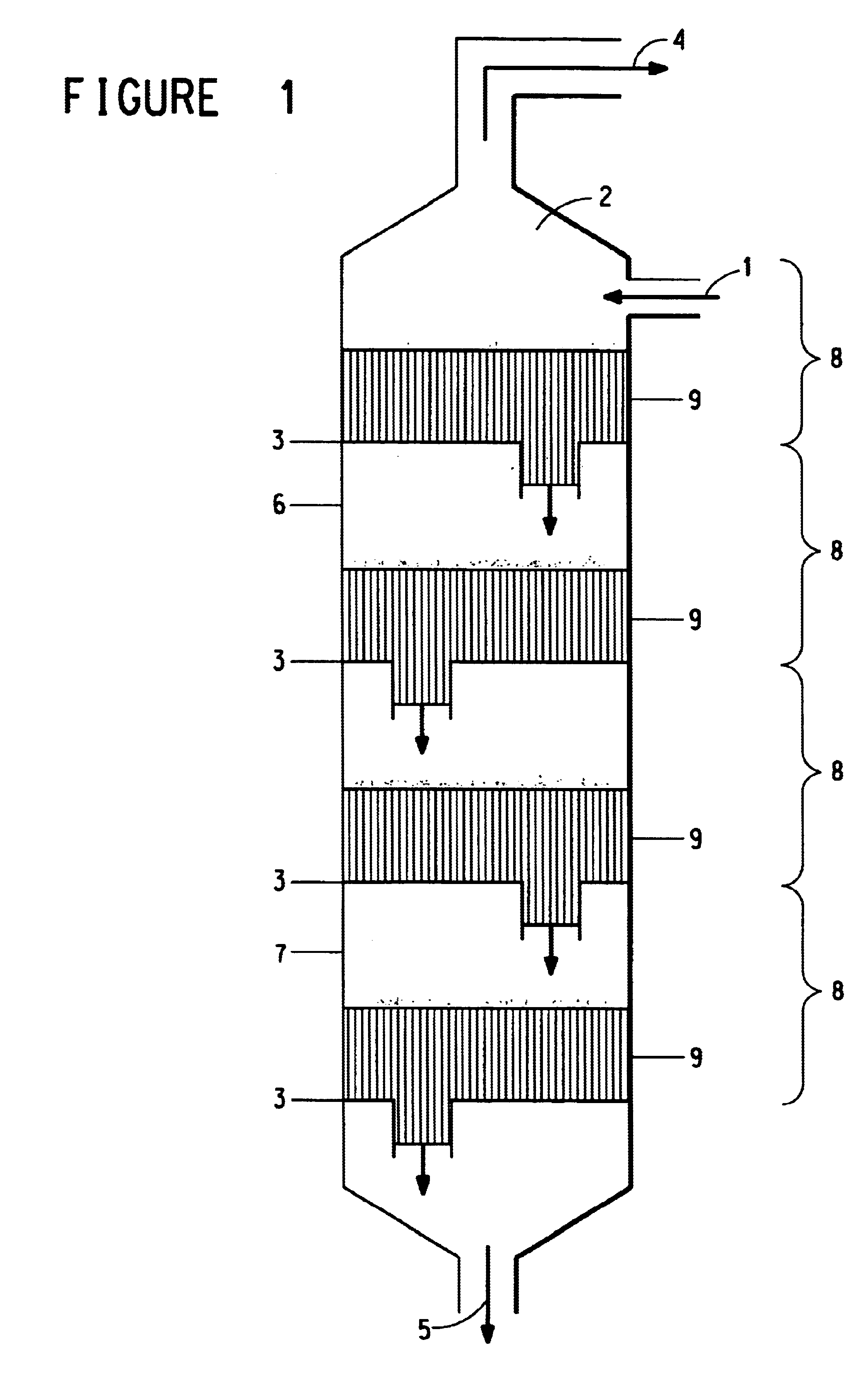
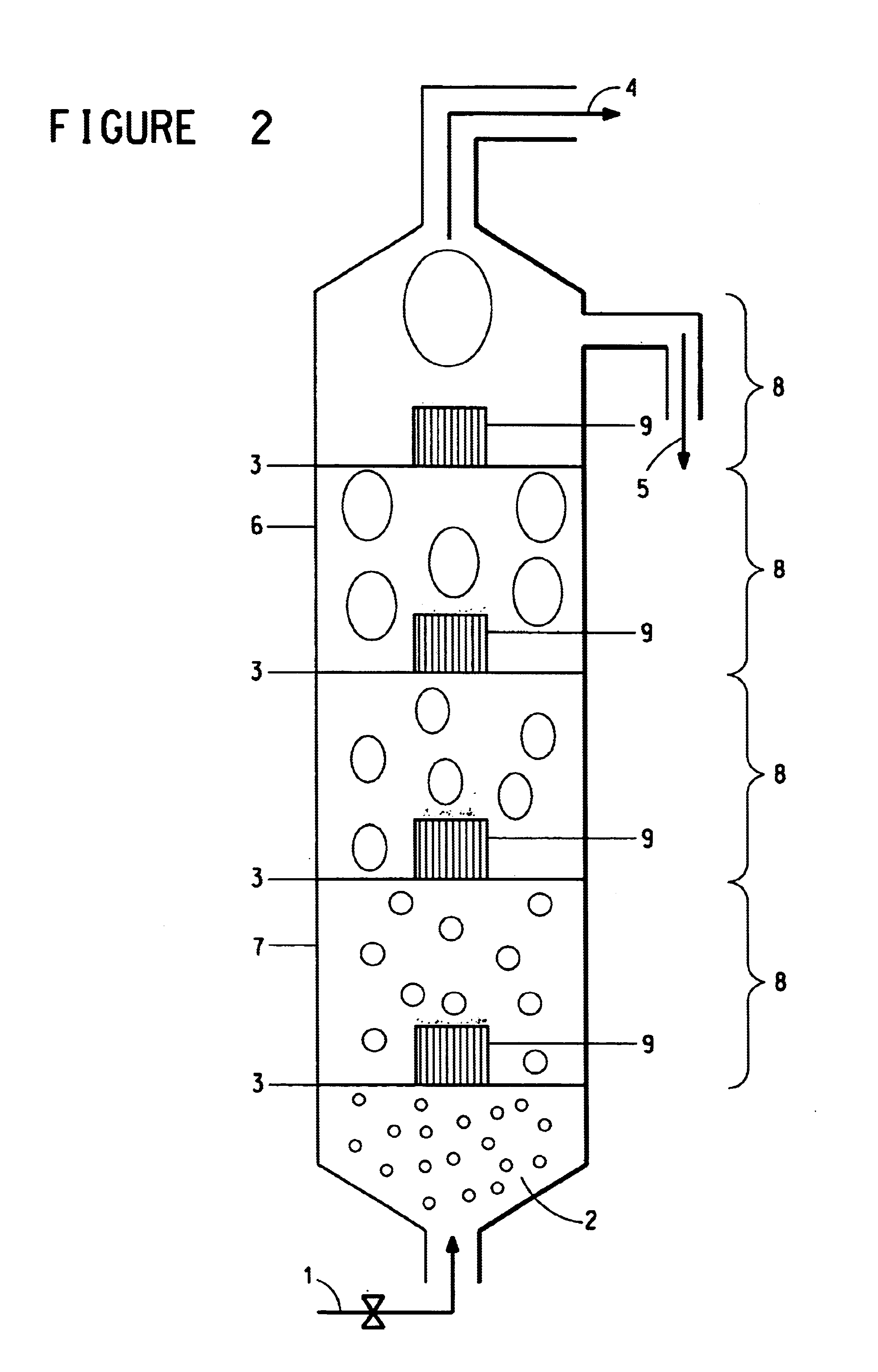
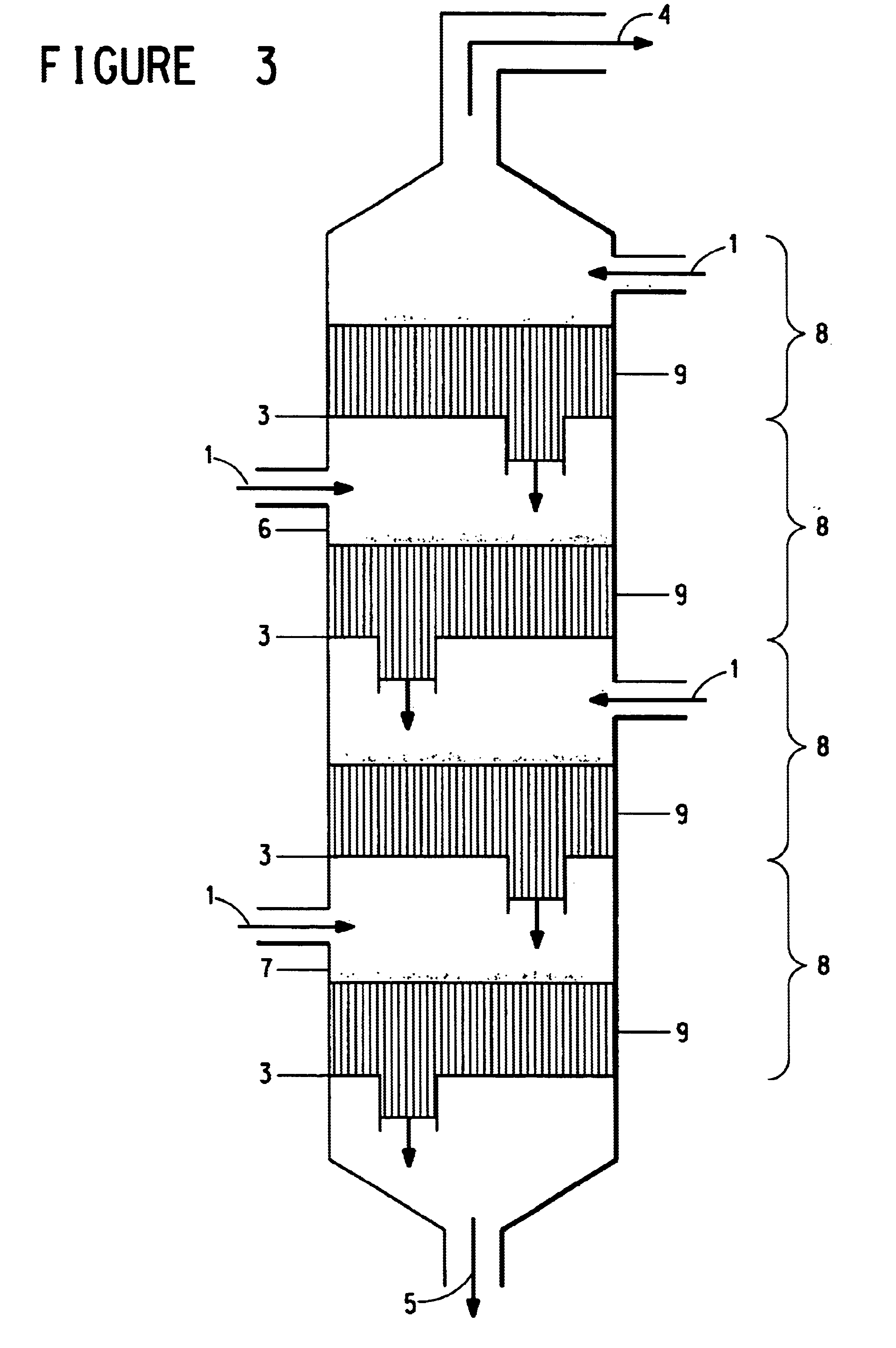
However, PPG has secondary hydroxyl end groups and it contains high percentages of terminal unsaturation.
However a successful manufacturing process for polytrimethylene ether glycol should provide the product within a desired time and under conditions to achieve the average molecular weight for end use applications and to limit the production of undesired chemical species that would make the product unsuitable for end use applications or that would require costly measures to remove.

Method used


Image

  • Continuous process for the preparation of polytrimethylene ether glycol
  • Continuous process for the preparation of polytrimethylene ether glycol
  • Continuous process for the preparation of polytrimethylene ether glycol

Examples


example 1

Dehydration of 1,3-propanediol in a Single Stage Column

In this example the flow-through reactive column used was a single stage Vigreux distilling glass column with a column length of 600 mm and 24 / 40 ground glass joints. It was obtained from Lab Glass Inc., Vineland, N.J. (Model No. LG-5890).

The glass column reactor sets atop a round-bottom flask and was equipped with a distillation head with a Liebig take-off condenser which was cooled by running water at ambient temperature. The condenser was fitted with a graduated fraction cutter and a distillate receiver. The Vigreux column was heated by wrapping with heater tape; it was insulated and maintained at 200.degree. C. and above. A hot oil condenser maintained at 110.degree. C. was utilized at between the top of the column and the distillation head to condense and recycle back any 3G vaporized in the column during the polymerization.

3G monomer with dissolved catalyst was introduced at the top of the Vigreux column, through a liquid ...

example 2

Dehydration of 1,3-propanediol in a Glass Bead Packed Column

The column of Example 1 was modified to increase the number of stages and to lengthen the residence time (and mixing) and to increase the yield. This example demonstrated the 3G continuous polymerization in a glass column reactor similar to that of Example 1, except that a single stage conventional distillation column packed with glass beads was used instead of the Vigreux column.

The column used in this example was a Hempel type distillation column of 500 mm in length and with 24 / 40 ground glass joints. (Lab Glass Inc, Vineland, N.J., Model No. LG-5820.) It is plain tube with a sealed-in glass honeycomb support for packing near the bottom. The column was packed with glass beads of 5 mm diameter (Lab Glass Inc., Model No. LG-6750-104).

In all other respects, the polymerization reactor was identical to that in Example 1. The residence time of 3G in the column under these conditions was about 1.5 minutes. Results of the 3G cont...

example 3

Dehydration of 1,3-propanediol in a Single Stage Glass Bead Packed Column with Multiple Passes

The conditions of Example 2 (bead packed column) were repeated to simulate a multi staged reactor. After a complete passing of the reaction mixture through the column as in Example 2, the collected effluent from the round bottom flask was passed through the column repeatedly. Run number 10 was thus a single pass experiment similar to runs 5-9 above. Run number 11 uses the product of run 10 as feed material. Run number 14 below, then, was the result of 5 passes through the single pass column simulating a 5 stage reactor. Yield was calculated from the amount of water condensate collected. Characterization of the products from run numbers 12, 13 and 14 is included in Table 6.


PUM

PropertyMeasurementUnit
temperatureaaaaaaaaaa

Abstract

The invention is a continuous process for the preparation of polytrimethylene ether glycol from 1,3-propanediol reactant. In addition, the invention is directed to a continuous multi-stage process comprising reacting at least one reactant in a liquid phase in an up-flow column reactor, and forming a gas or vapor phase by-product wherein the gas or vapor phase by-product is continuously removed at the top and at least one intermediate stage.

Description

This invention concerns a process and reactor for the preparation of polytrimethylene ether glycol from 1,3-propanediol reactant. In addition, the invention is directed to a continuous multi-stage process in an up-flow column reactor involving forming a gas or vapor phase by-product.TECHNICAL BACKGROUND OF THE INVENTIONKnown polyalkylene ether glycols include polyethylene glycol, poly-1,2-and 1,3-propylene ether glycol, polytetramethylene ether glycol, polyhexamethylene ether glycol and copolymers thereof. They have been used widely as lubricants or as starting materials for preparing lubricants used in the molding of rubbers and in the treatment of fibers, ceramics and metals. They have also been used as starting materials for preparing cosmetics and medicines, as starting materials or additives for water-based paints, paper coatings, adhesives, cellophane, printing inks, abrasives and surfactants and as starting materials for preparing resins, such as alkyd resins. They have also ...

Claims


Application Information

Patent Timeline
Patent Type & Authority Patents(United States)
IPC IPC(8): B01J19/24B01J8/04B01D3/00B01J10/00C07C41/00C07C41/09C08G65/00C08G65/34C07C43/11
CPCB01D3/009B01J8/0453B01J10/002B01J10/007B01J19/24B01J19/245C07C41/09C08G65/34C07C43/135B01J2208/00017B01J2208/00115B01J2219/00033B01J2219/00051B01J2219/00166B01J2219/00182B01J2219/185Y02P20/10
Inventor SUNKARA, HARI B.MARCHILDON, ERNEST KEITH ANDREWNG, HOWARD CHUNG-HOMANZER, LEO E.
Owner DUPONT CA
Why Eureka
Try Eureka