
Current switched magnetoresistive memory cell

Inactive Publication Date: 2004-06-01
NVE CORP
View PDF15 Cites 278 Cited by
  • Summary
  • Abstract
  • Description
  • Claims
  • Application Information

AI Technical Summary

Benefits of technology

The present invention provides a ferromagnetic thin-film based digital memory cell formed on a substrate supporting a bit structure with a memory film of an anisotropic ferromagnetic material capable of conducting an electrical current therethrough with a source layer positioned on one side thereof also capable of conducting an electrical current therethrough so that a majority of conduction electrons passing therefrom have a selected spin orientation to be capable of reorienting the magnetization of the memory film. A disruption layer is positioned on another side of the memory film capable of conducting an electrical current therethrough so that conduction electrons spins passing therefrom are substantially random in orientation. The magnitude of currents needed to operate the cell can be reduced using coincident thermal pulses to raise the cell temperature.

Problems solved by technology

In this situation, the magnetic environment can become quite complex with fields in any one memory cell affecting the film portions in neighboring memory cells.
Also, small ferromagnetic film portions in a memory cell can lead to substantial demagnetization fields which can cause instabilities in the magnetization state desired in such a cell.
One of the difficulties in such memories is the need to provide memory cells therein that have extremely uniform switching thresholds and adequate resistance to unavoidable interjected magnetic field disturbances in the typical memory cell state selection scheme used.
Such a coincident interjected magnetic fields memory cell state selection scheme is very desirable in that an individual switch, such as that provided by a transistor, is not needed for every memory cell, but the limitations this selection mode imposes on the uniformity of switching thresholds for each memory cell in a memory make the production of high yields difficult.
With or without such thermal pulse techniques, however, as the dimensions of magnetoresistive elements in memory cells shrink to less than 100 nm in size, the problems that must be overcome in order to make successful operating magnetoresistive memories become more difficult.
These problems include increasing thermal instability when states thereof are not being switched because less thermal energy is needed to upset the state of smaller memory cells, the needing of larger current densities to overcome greater demagnetization fields to store information, and the greater stray field interactions between adjacent memory cells on a common substrate.

Method used


Image

  • Current switched magnetoresistive memory cell
  • Current switched magnetoresistive memory cell
  • Current switched magnetoresistive memory cell

Examples


Embodiment Construction

In high-density magnetic memory cell arrays, a common problem is to make the memory cells magnetically stable (so they retain information indefinitely without requiring energy) while also being easily switchable between alternative memory states as the basis for storing binary bits of data. The switching of one cell must not disturb the magnetic state of another nearby cell in the array. Such highly controllable switching events are desired to be performed using as little time and energy as possible.

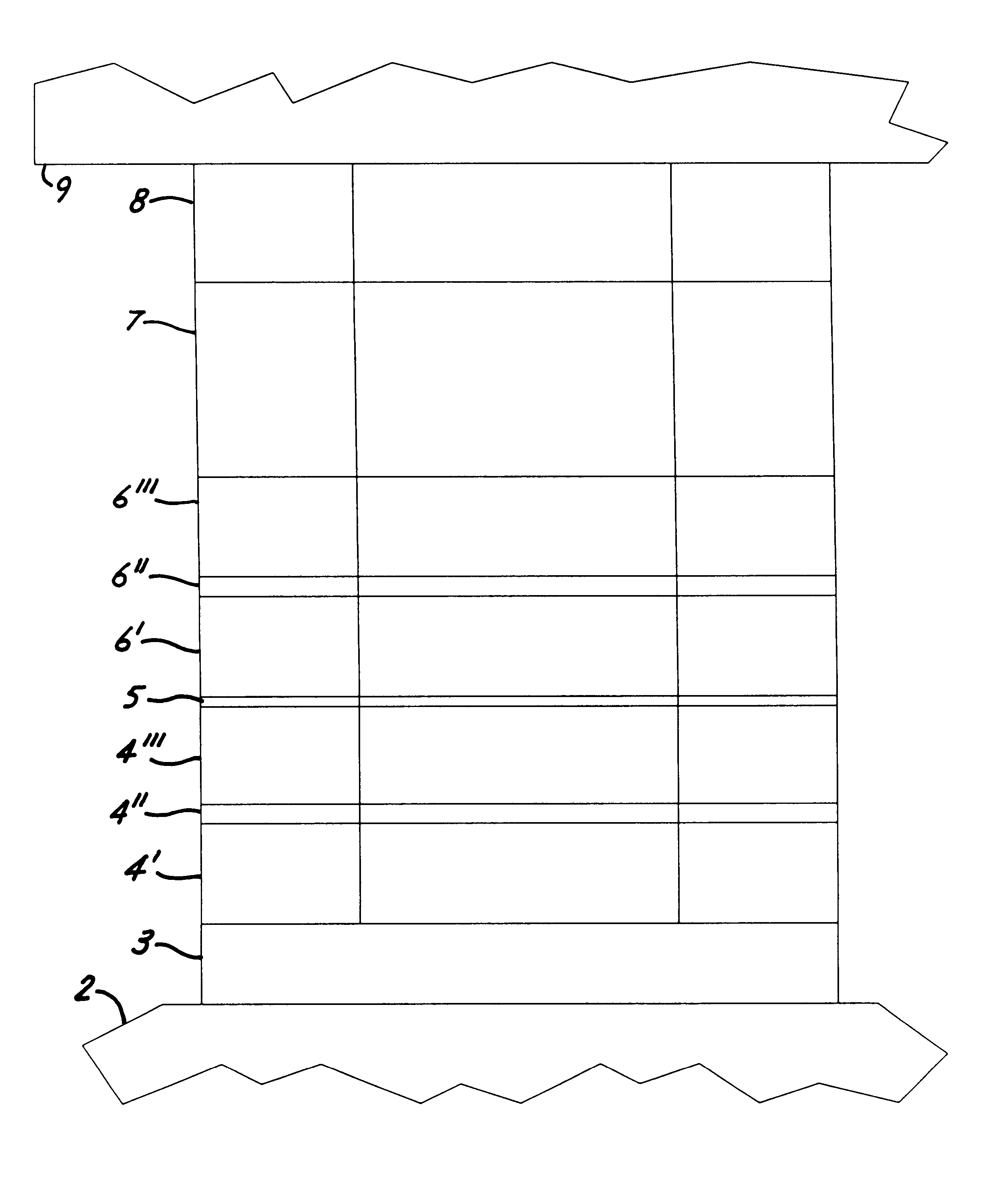
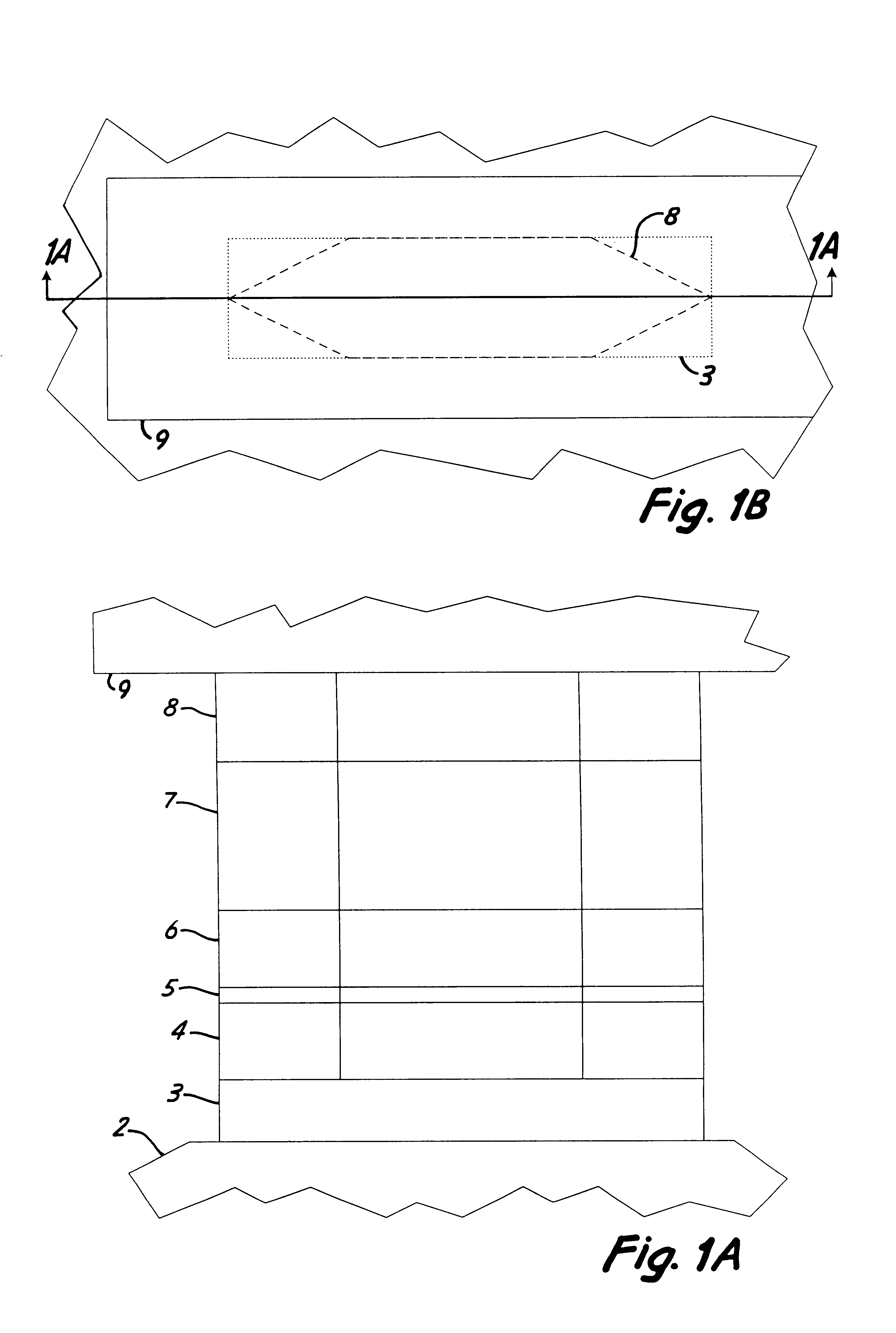
In the case of both spin valve and magnetic tunnel junction devices described above, the purpose of the spacer layer is to keep the magnetizations of the free and fixed magnetic material layers separated from coupling to one another while allowing passage of electrons between these two layers. In a properly constructed spin valve or magnetic tunnel junction device, the passage of electrons through the metallic Cu spacer layer 5, or the insulating Al.sub.2 O.sub.3 spacer layer 5, does not...


PUM


Abstract

A ferromagnetic thin-film based digital memory cell with a memory film of an anisotropic ferromagnetic material and with a source layer positioned on one side thereof so that a majority of conduction electrons passing therefrom have a selected spin orientation to be capable of reorienting the magnetization of the film. A disruption layer is positioned on the other side of the memory film so that conduction electrons spins passing therefrom are substantially random in orientation. The magnitude of currents needed to operate the cell can be reduced using coincident thermal pulses to raise the cell temperature.

Description

BACKGROUND OF THE INVENTIONThe present invention relates to ferromagnetic thin-film structures exhibiting relatively large response magnetoresistive characteristics and, more particularly, to such structures used for the storage and retrieval of digital data.Many kinds of electronic systems make use of magnetic devices including both digital systems, such as memories, and analog systems such as magnetic field sensors. Digital data memories are used extensively in digital systems of many kinds including computers and computer systems components, and digital signal processing systems. Such memories can be advantageously based on the storage of digital symbols as alternative states of magnetization in magnetic materials provided in each memory storage cell, the result being memories which use less electrical power and do not lose information upon removals of such electrical power.Such memory cells, and magnetic field sensors also, can often be advantageously fabricated using ferromagne...

Claims


Application Information

Patent Timeline
IPC IPC(8): H01F10/193H01F1/40H01F10/00H01F10/32H01F10/10G11C11/16G11C11/02
CPCB82Y25/00G11C11/16H01F1/408H01F10/1936H01F10/3268H01F10/3272G11C11/161
Inventor DAUGHTON, JAMES M.POHM, ARTHUR V.TONDRA, MARK C.
Owner NVE CORP
Learn More