However, although DMD-based projectors demonstrate some capability to provide the necessary light
throughput,
contrast ratio, and color
gamut, inherent resolution limitations (with current devices providing only 1024.times.768 pixels) and high component and
system costs have restricted DMD acceptability for high-quality digital cinema projection.
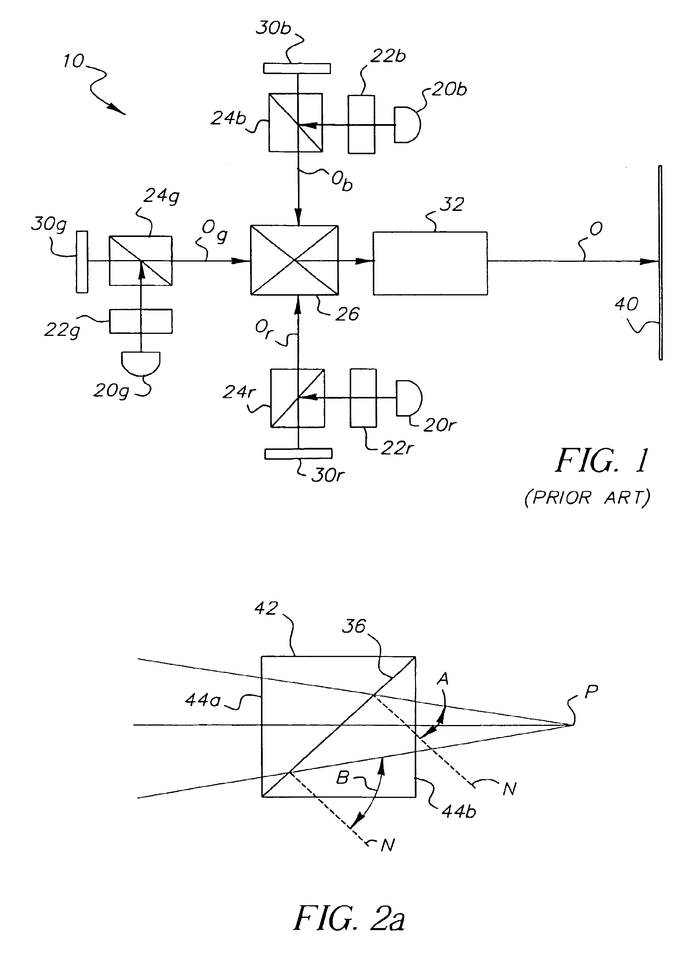
Significantly, the disclosure of U.S. Pat. No. 5,345,262 illustrates one of the major problems with the convergent projection approach: namely, that the separate color images must be properly registered on the projection surface.
Misregistration or poor focus along any one of the color light projection paths can easily result in an unsatisfactory image.
However, other problems inherent to a convergent approach remain.
One notable problem with approaches similar to that disclosed in U.S. Pat. No. 5,907,437 is a relatively high etendue.
As a general rule, increased etendue results in a more complex and costly optical design.
Moreover, although the configuration disclosed in U.S. Pat. No. 5,907,437 handles light from three times the area of the final multicolor image formed, this configuration does not afford any benefit of increased brightness, since each color path contains only one-third of the total
light level.
In particular, the second
relay lens and the
projection lens of a convergent
optics system such as that disclosed in U.S. Pat. No. 5,907,437 are inherently constrained by a large etendue, which adds cost and complexity to such a solution.
At the same time, different segments of the
relay lens and of the projection lens
handle different wavelengths, so that localized lens imperfections, dust, or
dirt not only affect the projected image, but can
impact the
color quality.
In light, then, of etendue constraints, of
color correction requirements, of dust and
dirt sensitivity, and of the need for maximizing brightness levels for digital projection, there appear to be significant inherent limitations that hamper the convergent approach exemplified in U.S. Pat. No. 5,907,437.
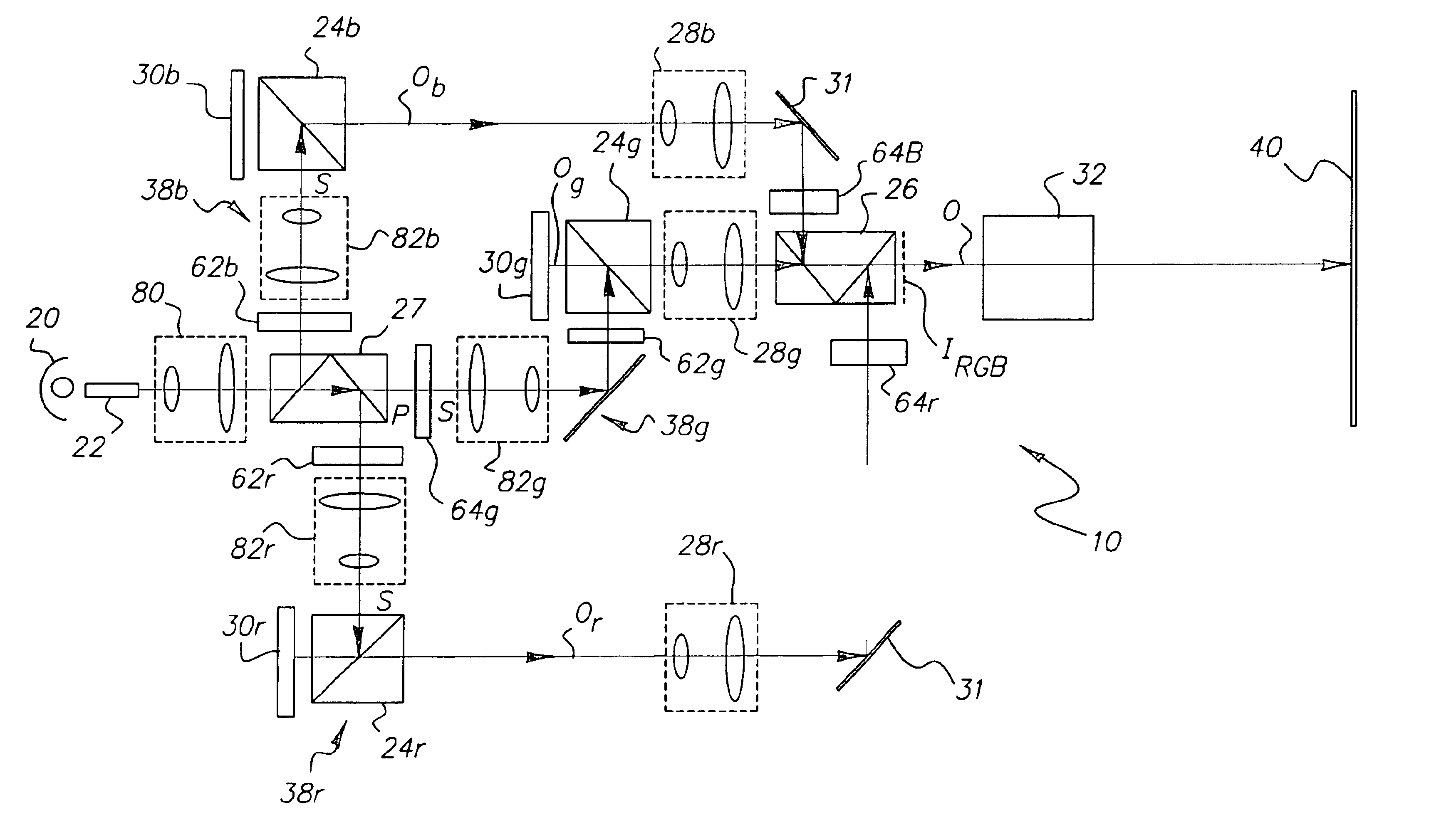
Dichroic coatings used for dichroic combiner 26 can be expensive and difficult to design and fabricate for suitable performance with incident light over a wide range of angles, particularly in projection applications where high brightness levels and a broad color
gamut are needed.
However, in practice, it has been shown to be difficult to obtain these advantages for digital projection apparatus, due to the need to maintain high brightness levels at the same time.
For example, it would be difficult to produce a deep red color using a
red light channel that also includes some
green light.
However, even slight tolerance errors in X-cube fabrication can result in imaging problems when these devices are used with conventional digital projection solutions.
For example, slight misalignment of the planar coated surfaces within the X-cube could cause aberrations such as color fringing.
Fabrication of a high-quality X-cube is further complicated by the requirement that individual component prisms have identical refractive indices; in practice, this is best accomplished when the same glass melt is used for all
prism components.
Further problems are a result of the difficulties in providing uniform, flat surfaces on outer faces of the assembled X-cube.
It can be well appreciated that this complexity adds considerable cost to the X-cube.
Finally, obtaining brightness using conventional approaches results in
high heat levels, which can damage adhesives and
coating surfaces of the X-cube.
Notably, however, improved brightness is not achieved by the design in U.S. Pat. No. 6,113,239, since the angular constraints of dichroic surfaces have not been alleviated.
Other problems include costly coatings solutions, since polarizing beamsplitter coatings are not readily optimized for all color and polarization combinations.
However, this arrangement would not be well-suited for
projector apparatus using reflective spatial light modulators, since back working distance requirements are still excessive.
Moreover, the solution disclosed in U.S. Pat. No. 5,944,401 does not address the inherent angular limitations of dichroic surfaces described above.
For example, the design noted in U.S. Pat. No. 5,597,222 fails to address inherent angular dependencies in the dichroic
coating response, so that it remains difficult to support a large color gamut while maintaining image brightness at the same time.
Moreover, the projection lens must also use a
high numerical aperture with this design, which implies added cost over designs with lower numerical aperture.
With a large number of optical components in the path of a polarized illumination source, some unavoidable stress
birefringence would necessarily alter the polarization states of both unmodulated and modulated light traveling in both directions, resulting in loss of
image contrast.
While the approach disclosed in U.S. Pat. No. 5,357,289 eases the demands on projection lens design, the imaging relay (first lens group) presents a challenge, since it must provide a long working distance for the spatial light modulators and associated PBS and color-combining V-
prism.
The solution in U.S. Pat. No. 6,247,816 addresses a component
packaging problem, but does not alleviate any of the angular constraints imposed by dichroic combiner response.
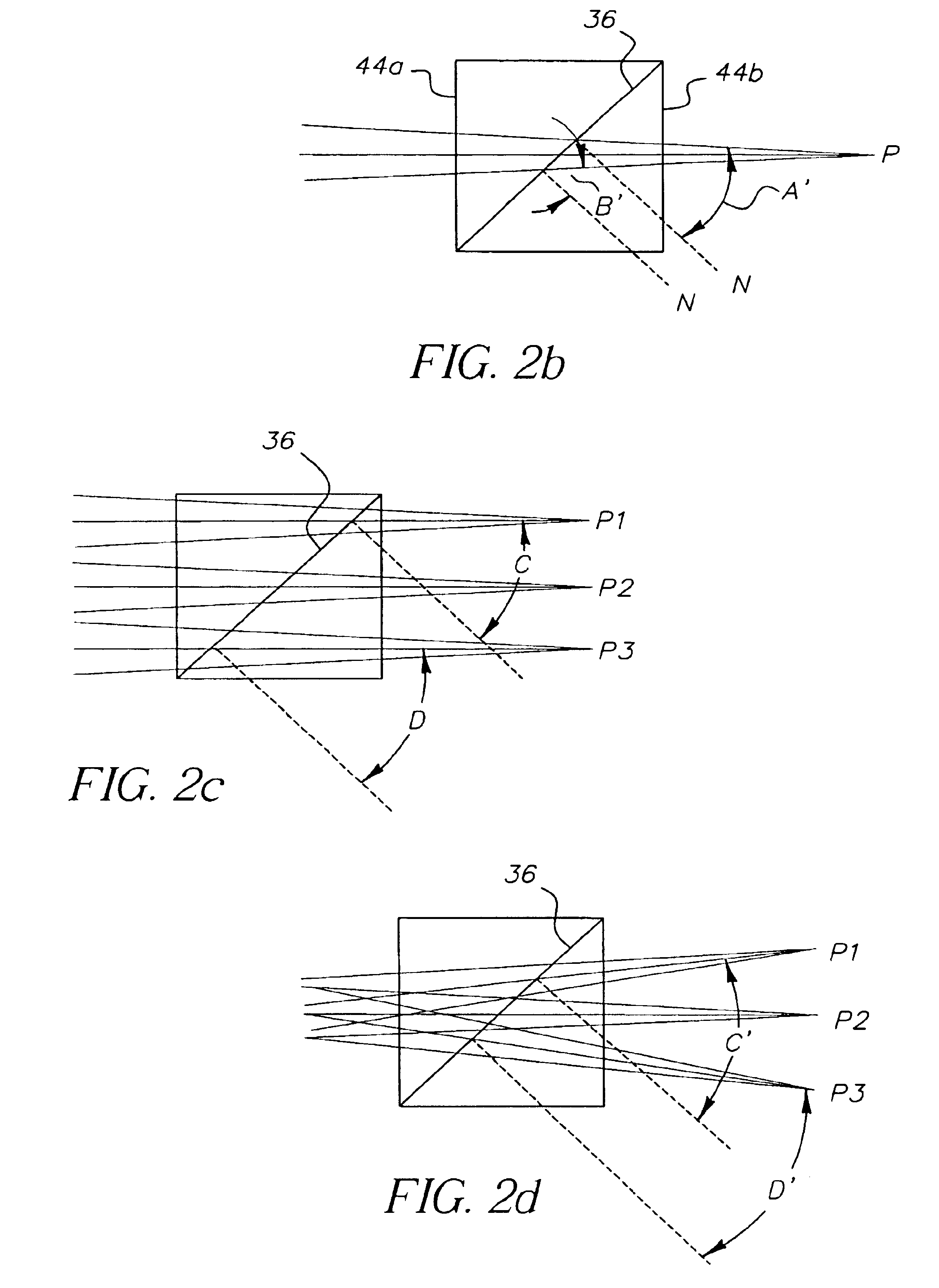
However, as is noted above with reference to FIGS. 2a-2d, the performance of dichroic surfaces used for combining
color image paths is hindered by the large incidence angles of low f / # optical systems.
In
spite of their high cost and known problems, X-cubes have served as dichroic combiners in a substantial number of imaging device designs.
At the same time, however, the solution disclosed in U.S. Pat. No. 6,231,192 does not alleviate the back working requirements of the projection lens
system.
This solution limits the f / # of
projector optics to slower speeds, constraining the available brightness and requiring larger projection lens diameters.
As can be expected, the same performance problems related to light incident angle apply whether dichroic coatings are used to combine modulated light into the projection path or are used to separate unmodulated light in the illumination path.
When dichroic surfaces receive incident light at varying angles, output performance is affected, causing perceptible color shifts across the field.
It is difficult to correct for this slight color shading; graduated filters are expensive to design and reduce the overall brightness available.
However, this would be difficult to achieve without increasing the bulk and cost of uniformiizing components.
Further problems present themselves.
For example, where an integrating bar is used as a light uniformizer, it would not be sufficient merely to make the integrating bar larger in cross-section.
Similar problems limit solutions using other types of uniformizing components.
Such solutions are made more difficult by the need to maximize light at the spatial light modulator itself, providing incident light at a
high numerical aperture.
Existing designs admit some degree of
color shift; conventional approaches for correcting
color shift would require more costly dichroic coatings and entail some additional loss of brightness in both illumination and modulation
optics paths.

