Regeneration of biosensors

a biosensor and biosensor technology, applied in the field of biosensor regeneration, can solve the problems of long time drift, short life, frequent calibration and short life, and both a complicated solution and an increase in cos

Inactive Publication Date: 2004-11-02
SENZIME
View PDF7 Cites 270 Cited by
  • Summary
  • Abstract
  • Description
  • Claims
  • Application Information

AI Technical Summary

Benefits of technology

In a second aspect of the invention there is also provided a system for long time measurements of whole blood directly and continuously sampled from a patient, wherein the flow of the sampled blood is held at a very low rate.

Problems solved by technology

However, interference with reducing / oxidizing substances causes problems like long time drift, need for frequent calibration and short life.
This is both a more complicated solution and also more expensive, since the dialysis cassette has to be replaced before a new measurement can be made.
The enzyme calorimeter disclosed therein is however not suited for direct measurement on whole blood, since the blood cells quickly will clog the column containing the immobilized enzyme, due to adsorption of blood constituents such as various cells, trombocytes, proteins etc.
This effect could be circumvented to a certain extent by diluting the blood at least ten times, which will reduce the sensitivity of the measurement considerably.
However such a measure would require an extra supply of a diluting solution.
This support made from agarose, is however softer than the conventional support materials used in this field, preferably glass, and therefore are at a certain risk of (occasionally) being compressed by the blood sample, which in turn quickly will clog the column.
Thus, at present there is no reliable method and system available for the direct and continuous analysis of whole blood drawn from patients.
The latter process is however a slow process compared to the diffusion controlled enzyme reaction.
It is self evident that the flow rate will decrease drastically when the blood enters the large dead space 119 inside the coupling, thereby giving the blood constituents time to adhere to the inner surface of the connector and eventually clog the connector.

Method used


Image

  • Regeneration of biosensors
  • Regeneration of biosensors
  • Regeneration of biosensors

Examples


example i

(Comparative)

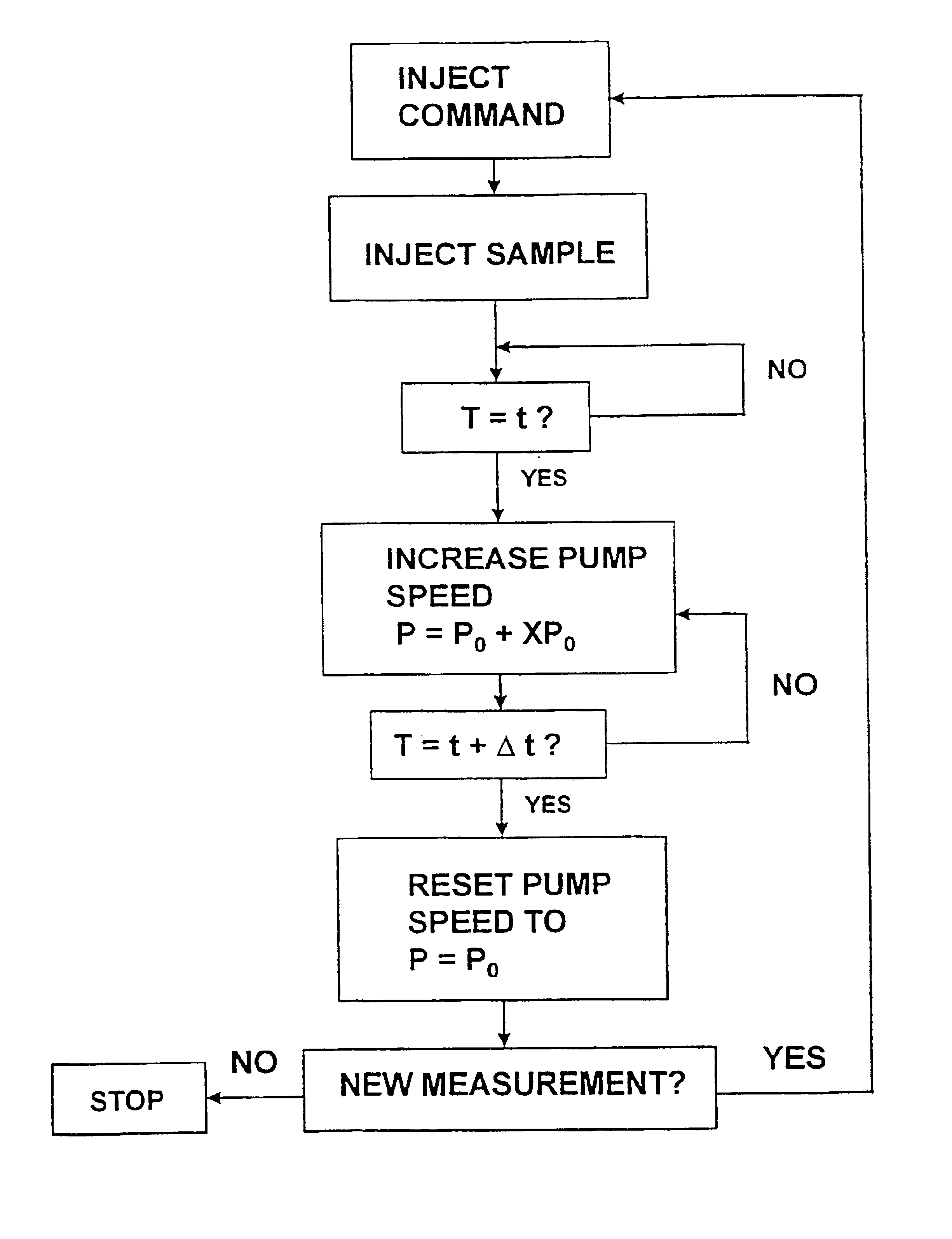
In this example the flow was kept constant, and thus no increased flow was applied. The sample (blood) volume was 5 .mu.l, and the base line signal was recorded before and after detection was made. Three consecutive runs were performed.

As is clearly demonstrated the baseline signal before detection increases from 0.10 to 0.22 V, and also the baseline signal after detection increases from 0.15 to 0.34 V.

example ii

(Comparative)

The experiment of Example I was repeated with a fresh sensor and new samples.

Again the base line signals clearly are not reproducible between runs.

example iii

(Comparative)

In this example the flow was also kept constant but a sample prepared from a standard solution and glucose was introduced, and passed through the reactor.

As can be seen, the base line signal is not affected.


PUM

PropertyMeasurementUnit
pore sizeaaaaaaaaaa
volumesaaaaaaaaaa
timeaaaaaaaaaa

Abstract

The invention comprises a method of regenerating a biosensor. It involves passing a background flow of fluid without reactive components through the flow passage. At a selected point in time a sample aliquot is injected into said background flow. At a point in time when a signal from said sensor is obtained the flow rate of the background fluid is increased. The invention also comprises a system for continuous monitoring of analytes in a biological fluid, the system having increased life by virtue of inherent regeneration of sensors employed. It comprises a biosensor (26, 30, 32), a sampling device (4) for providing a sample of said biological fluid, and means (10, 15, 18, 24) for passing a flow of a background fluid through said flow passage at selectable flow rates, means (20, 50, 55) for injecting said sample into said flow of background fluid, and means (50, 55) for increasing the flow rate of said combined flow. Means for achieving a washing action at the signal generating portion are provided.

Description

The present invention relates in general to the field of biosensors, and in particular to methods and apparatus for regenerating such sensors, thereby increasing the effective life thereof.In a specific aspect the invention relates to a system for continuous analysis of analytes in blood or serum comprising means for regeneration of the sensor employed therein.Measurements of analytes in blood is commonly performed by sampling blood from patients and analyzing said samples in a laboratory, often situated at a location remote from the ward. E.g. for glucose analysis there are available special reagent sticks usable for measuring on site i.e. in the ward. However, the accuracy of such measurements is questionable, and the error could be 10-20% at best.Often it is necessary to perform several sequential measurements over periods of several hours, which is very labor intensive. Furthermore, the risk for errors because of the human intervention is evident, and the low accuracy is of cour...

Claims


Application Information

Patent Timeline
Patent Type & Authority Patents(United States)
IPC IPC(8): C12Q1/00C12M1/40A61B5/145A61B5/1473G01N27/327G01N33/49
CPCC12Q1/001Y10T436/117497Y10T436/106664
Inventor CARLSSON, THOMAS
Owner SENZIME
Why Eureka
Try Eureka