Multiple plasma generator hazardous waste processing system

a technology of hazardous waste and plasma generator, which is applied in the direction of special packaging, lighting and heating equipment, packaging, etc., to achieve the effect of facilitating faster return of processing facilities and preventing abnormal deterioration of refractory linings

Inactive Publication Date: 2004-11-16
PLASCO ENERGY GROUP INC
View PDF5 Cites 145 Cited by
  • Summary
  • Abstract
  • Description
  • Claims
  • Application Information

AI Technical Summary

Problems solved by technology

Firstly, the chemical composition of the waste and / or hazardous material stream to be processed. The internal configuration and size of the reactor vessel are dictated by the operational characteristics through analyses of the input waste stream to be processed.

Method used


Image

  • Multiple plasma generator hazardous waste processing system
  • Multiple plasma generator hazardous waste processing system
  • Multiple plasma generator hazardous waste processing system

Examples


Embodiment Construction

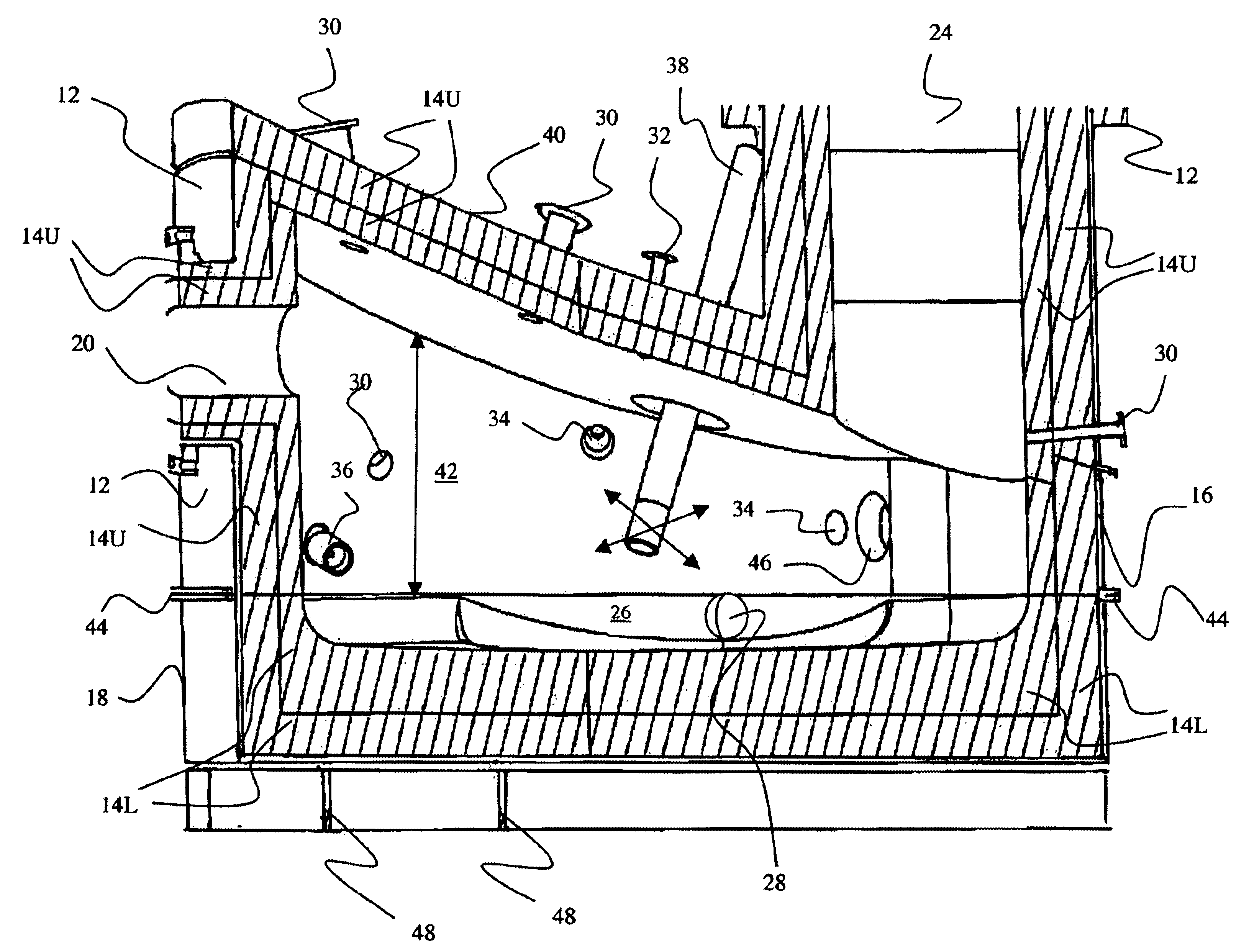
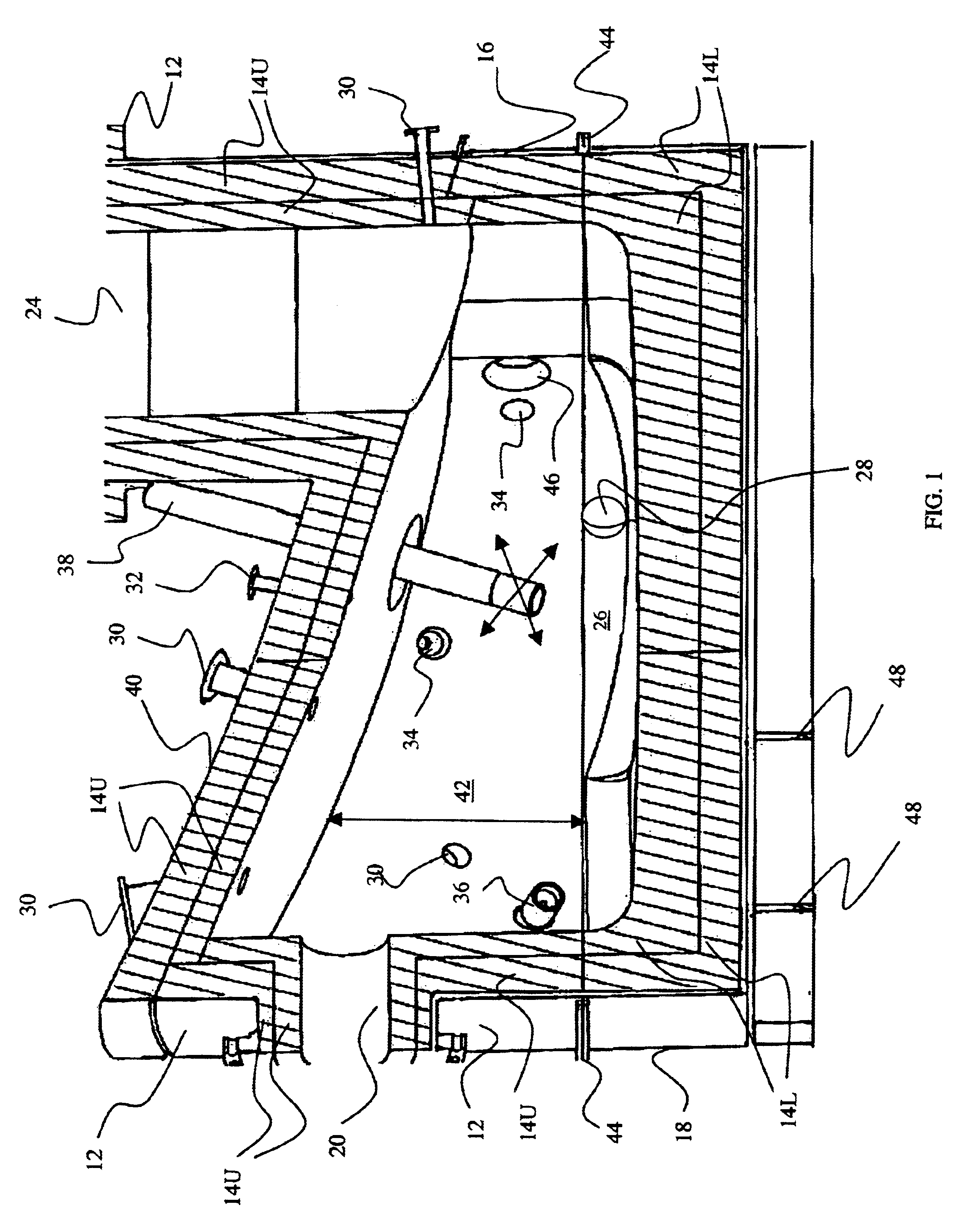
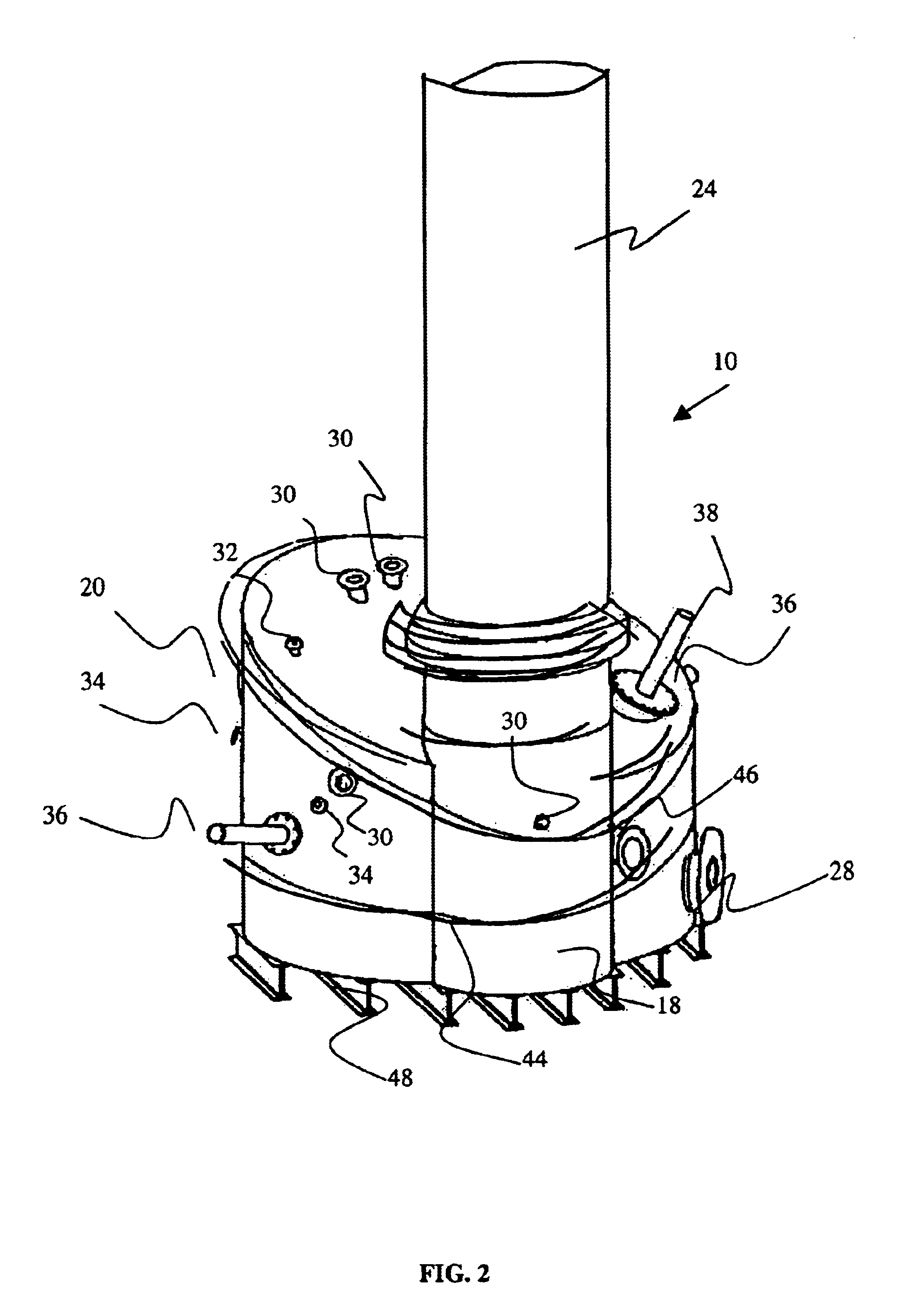
One embodiment of an aspect of the present invention includes three plasma arc generators mounted in a cylindrical, refractory-lined reactor vessel with sloping top, as depicted in FIG. 1, FIG. 2 and FIG. 3, and as will be described in detail hereinafter. As seen therein, the cylindrical vessel 10 comprises a shell 12 in two sections, upper section 16 and lower section 18, each of which is lined with a refractory material 14U in upper section 16 and 14L in lower section 18. Examples of suitable refractory materials include ceramic blanket, insulating firebrick and high alumina hot face brick, possibly with smaller amounts of chromium oxide, zirconium oxide or magnesium oxide.

As previously discussed, the lower section 18 of the vessel 10 is subject to more degrading environments and so the refractory material 14L is a much more robust refractory material. Examples of such more robust refractory materials include DIDIER DIDOFLO 89CR and RADEX COMPAC-FLO V253.

The vessel 10 is provided ...


PUM

PropertyMeasurementUnit
temperatureaaaaaaaaaa
operating temperatureaaaaaaaaaa
temperatureaaaaaaaaaa

Abstract

A waste processing system is provided herein which entails the use of at least one fixed-position plasma arc generator for primary processing and at least one moveable plasma arc generator for secondary processing assistance and / or final conditioning of the slag prior to exit from the reactor vessel. This optimum processing environment is provided by control of reactor vessel configuration and real time control of processing characteristics to ensure maximum processing efficiency.

Description

1. Field of the InventionThis invention relates to a method and a system for the disposal of waste and / or hazardous materials waste.2. Description of the Prior ArtA major problem facing modern society is the disposal of toxic waste and / or hazardous materials in a manner which minimizes harmful effects on the environment. Such a disposal system is one which is capable of reducing such toxic and / or hazardous waste to compounds which are suitable for environmental disposal. Such suitability is, of course, defined in terms of acceptable levels of pollution, and is determined by a variety of regulatory agencies.Traditionally, hazardous waste disposal has taken the form of direct burial in landfills, or simple thermal processing of the waste, followed by burial of the solid residue, and release to the atmosphere of the volatile residue. None of these approaches have proven acceptable, due to the fact that the materials which are released to the environment tend to remain as unacceptable s...

Claims


Application Information

Patent Timeline
Patent Type & Authority Patents(United States)
IPC IPC(8): C10J3/18C10J3/02F23G5/027F23G5/50F23G5/08F23G7/00F23L7/00A62D3/00
CPCF23G5/027F23G5/085F23G5/50F23G7/00F23L7/005C10J3/18A62D2203/10Y02E20/16C10J2200/09C10J2300/0946C10J2300/0973C10J2300/1238F23G2201/701F23G2202/20F23G2204/201F23G2900/55002F23L2900/07009B09B3/00F23G5/08
Inventor TSANGARIS, ANDREAS V.CARTER, GEORGE W.SHEN, JESSE Z.FEASBY, D. MICHAELCAMPBELL, KENNETH C.
Owner PLASCO ENERGY GROUP INC
Why Eureka
Try Eureka