
Endoscope

a technology of endoscope and endoscope, which is applied in the field of endoscope, can solve the problems of unbalanced image distortion and expansion

Inactive Publication Date: 2004-11-16
INTUITIVE SURGICAL OPERATIONS INC
View PDF19 Cites 112 Cited by
  • Summary
  • Abstract
  • Description
  • Claims
  • Application Information

AI Technical Summary

Benefits of technology

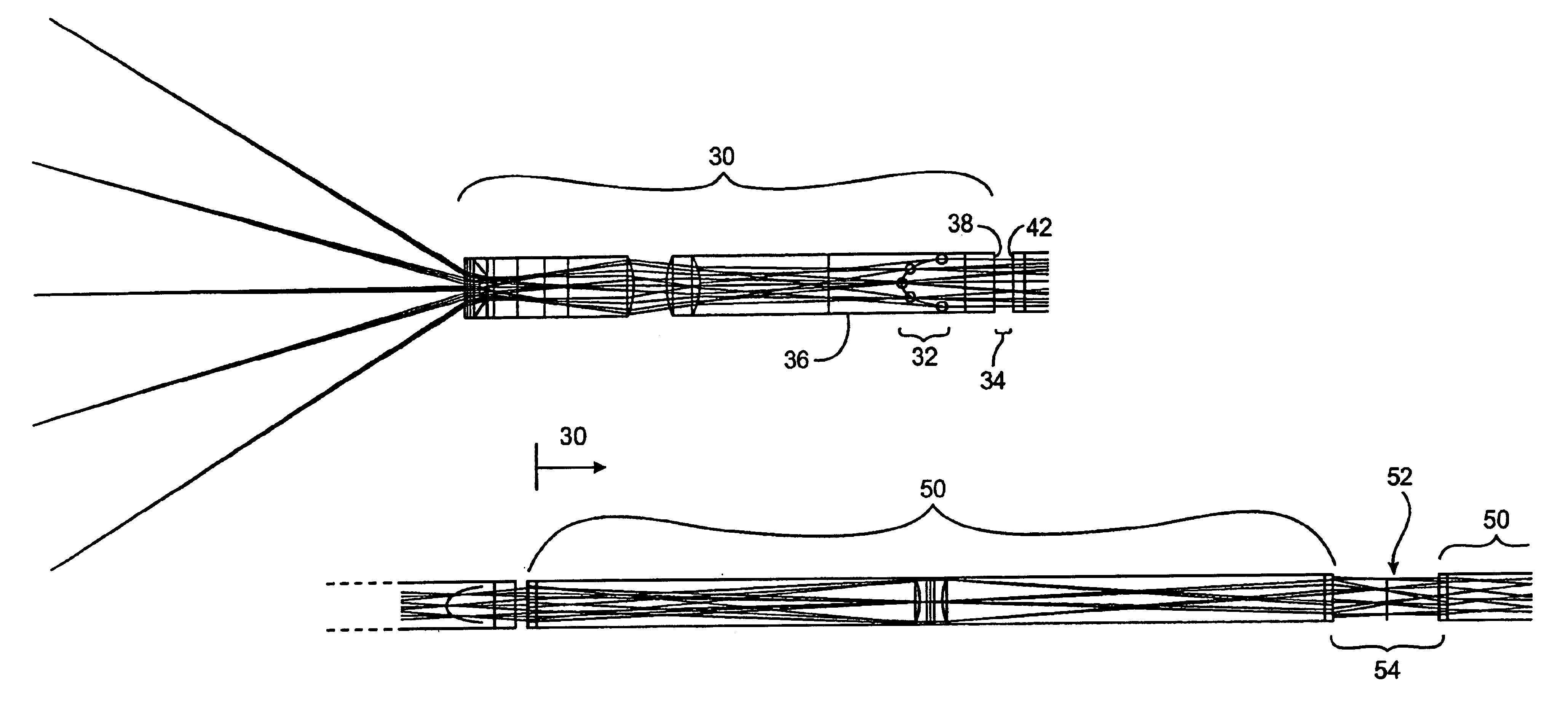
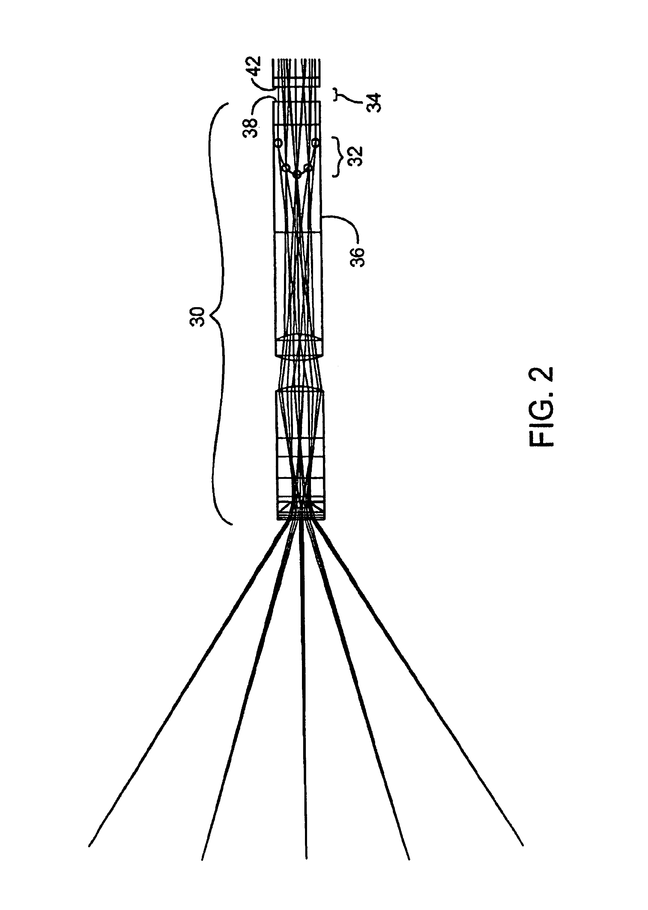
Surprisingly, by making use of a first and / or last intermediate image disposed within a lens of an integrally designed optical train, the endoscopes of the present invention will generally provide a significantly larger Numerical Aperture than known endoscopes having similar cross-sectional dimensions and length. Consequently, the optical train will produce a highly aberration corrected image with a better image resolution. Forming these intermediate images within glass also decreases the sensitivity of the image quality to dust and / or scratches, which further enhances the viewer's ability to detect small details in the image.
In contrast to known endoscopes, which balance or correct the image at the objective lens system and ocular lens system independently, the endoscopes of the present invention will typically deliver a distorted or unbalanced image from the objective lens system through the relay lens system to the ocular lens system. After the distorted image has been delivered to the ocular lens system, the aberrations in the distorted image are balanced and compensated by the ocular lens system to produce the final image. By delivering an expanding, unbalanced, and distorted image to the ocular lens system, the endoscopes of the present invention are able to achieve a larger throughput relative to conventional endoscopes having the same cross section and length of endoscope, while at the same time reducing the amount of aberrations introduced into the image throughout the optical train. Consequently, a brighter, clearer final image can be created.
Causing an image to coincide with an optical element instead of air, increases the ability of the optical train to image a particular object and causes the optical train to behave as if it had a much larger Numerical Aperture. The invention also permits the image to be less affected by dust or scratches on lens surfaces that would normally harm the image's quality and so affect the viewer's ability to detect small details in the image.
In another aspect, the present invention provides a method of manipulating an image captured by a stereoscopic endoscope. A diopters of the captured image is set. The magnification of an image is independently altered without significantly affecting the diopters. The X-Y positioning of the image is adjusted without introducing aberrations or affecting the diopters and magnification, and an orientation of the captured image is rotated such that the rotation of the image does not affect the diopters, magnification, and X-Y positioning of the captured image.
The X-Y positioning of the image can be adjusted so that there are reduced (less than 1%) aberrations introduced into the diopters and magnification. The orientation of the captured image can also be independently adjusted without affecting the diopters, magnification, or X-Y positioning of the image.
In many configurations, the unbalanced image is distorted and expanding. Such a configuration therefore can provide the maximum throughput of optical information through the lens systems. This permits better image resolution and improved image brightness, relative to a conventional lens systems in which the objective and ocular systems are independently balanced.

Problems solved by technology

In many configurations, the unbalanced image is distorted and expanding.

Method used


Image

  • Endoscope
  • Endoscope
  • Endoscope

Examples


Embodiment Construction

While the invention will generally be described herein with reference to surgical optical imaging devices and methods, the invention has applications for any lens systems that transfer optical information through a relay (a series of small diameter lenses) such as, for example, monoscopes, stereoscopes, boroscopes, periscopes, arthroscopes, and the like.

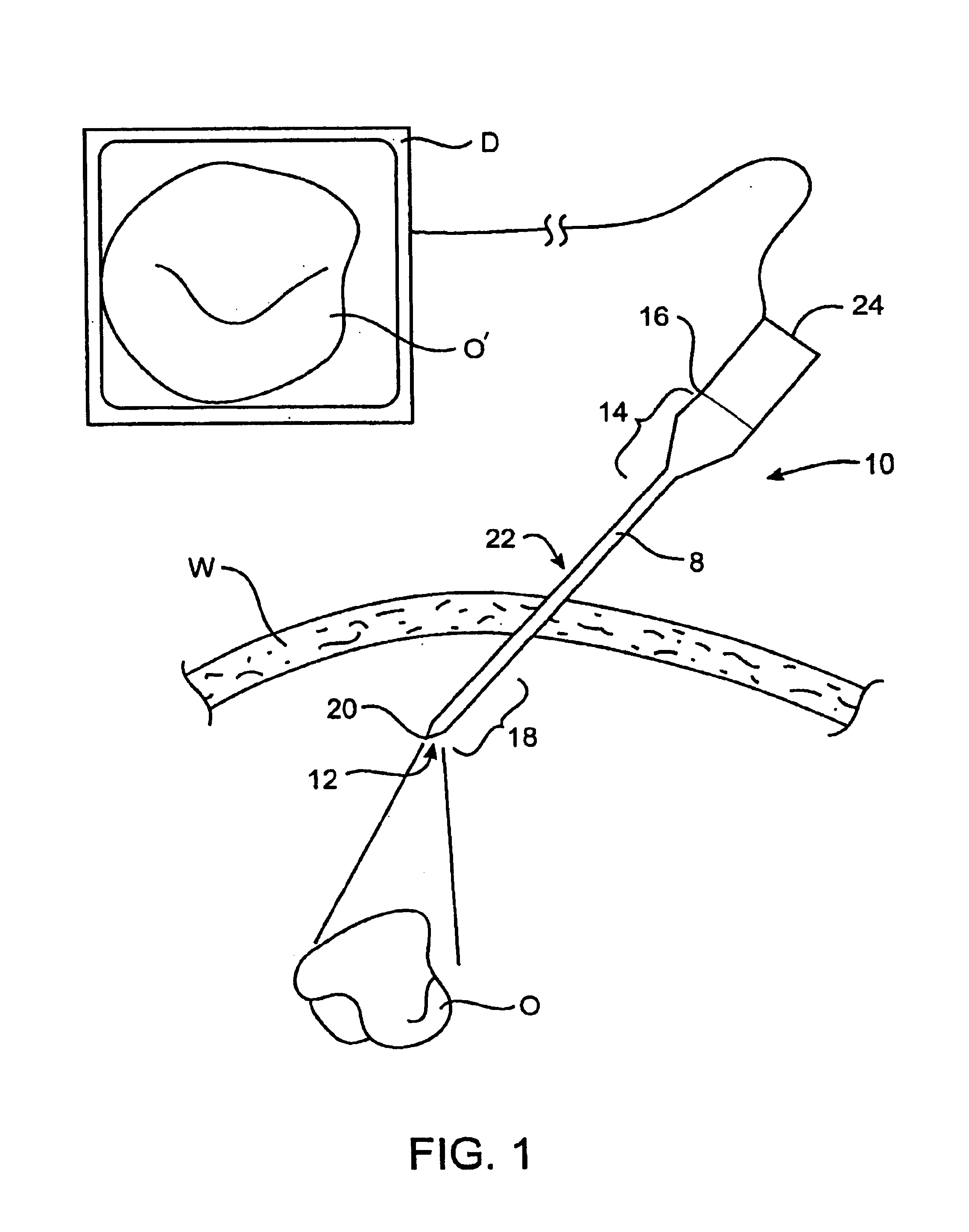
Referring now to FIG. 1, an endoscope 10 extends through a body wall W to an internal viewing site within a patient body. Endoscope 10 includes a shaft or body 8 containing an optical train 12. Endoscope 10 generally has a proximal portion 14 adjacent a proximal end 16, a distal portion 18 adjacent a distal end 20, and an intermediate portion 22 between the proximal and distal portions.

In use, an object O is within a field of view of endoscope 10, which transmits an image of the object O' proximally to a camera 24 optically coupled to proximal end 16 of the endoscope. Camera 24 will typically have a charge-couple device (CCD) or the ...


PUM


Abstract

Improved optical devices and methods transmit optical images along elongate optical paths with relatively limited cross-sectional dimensions using an improved objective, relay, and ocular systems. In a first aspect, at least one intermediate image formed within an optical component, rather than being formed in a gap between optical components. In a preferred embodiment, a first intermediate image is formed within glass of the most proximal objective lens, with the first intermediate image extending axially along a curved image location within the glass. The last intermediate image may similarly be disposed within a distal lens of the ocular system. By making use of a first and / or last intermediate image disposed in this manner within a lens, endoscopes can exhibit a significantly larger Numerical Aperture than known endoscopes having similar cross-sectional dimensions. In a second aspect, the ocular system allows independent adjustment of diopters, magnification, X-Y positioning, and rotation orientation of the captured image while introducing minimal aberrations.

Description

1. Field of the InventionThe present invention is generally related to optical devices and methods such as those used for surgery. In particular the present invention relates to techniques for enhancing the throughput and manipulation of optical information through a limited cross-section endoscopic relay. In one aspect, the invention provides an endoscope having an optical relay, objective, or ocular using at least one intermediate image formed within an optical component such as a glass element or lens. In another aspect, the invention provides an ocular system that permits independent adjustment of the diopters, magnification, X-Y positioning and rotational orientation of an image, while introducing minimal aberrations.Minimally invasive medical techniques are aimed at reducing the amount of extraneous tissue which is damaged during diagnostic or surgical procedures, thereby reducing patient recovery time, discomfort, and deleterious side effects. The average length of a hospital...

Claims


Application Information

Patent Timeline
Patent Type & Authority Patents(United States)
IPC IPC(8): A61B1/002G02B23/24G02B25/00A61B1/00A61B1/04
CPCG02B25/001A61B1/055G02B23/2446A61B1/00188A61B1/00193A61B1/042
Inventor FARR, MINABRAXMEIER, WOLFGANG
Owner INTUITIVE SURGICAL OPERATIONS INC
Learn More