Apparatus for electrically coating a hot-rolled steel substrate

Inactive Publication Date: 2005-01-04
ANDRITZ PATENTVERW GES
View PDF4 Cites 4 Cited by
  • Summary
  • Abstract
  • Description
  • Claims
  • Application Information

AI Technical Summary

Benefits of technology

An advantage of the present invention is that the pickling bath and the electroplating bath can be operated at relatively low temperatures of about 50° C. to about 90° C. in aqueous solutions. In addition, by electroplating the steel strip immediately after the pickling process, the overall process can be carried out efficiently and economically. The prior processes use a cold-rolled steel which must be annealed to a temperature of about 300-500° C. The annealed strip of steel is then coated with an oil to reduce corrosion and stored until ready for use. The oiled steel strip must then be cleaned before use and pickled before the cold-rolled steel can be electroplated. The present invention eliminates the annealing step and the cleaning step since the steel strip is electroplated immediately after the pickling step. The process of the invention results in reduced chemical consumption and reduces the amount effluent produced by the pickling and electroplating processes.
Referring to FIG. 1, the apparatus 10 includes a pickling section 12 and an electro-coating section 14. In the embodiment illustrated, the pickling section 12 includes two pickling tanks 16 and 18 connected in series. The pickling tanks 16 and 18 can be a conventional continuous feed type tank as known in the art. Although two pickling tanks are shown, additional tanks can be used in series as needed. Fresh pickling acid is supplied through a pipe 20 into the downstream pickling tank 18 adjacent the outlet end 22. The pickling acid flows through the pickling tank 18 and overflows into the pickling tank 16 either by a pump or through a weir. The upstream pickling tank 16 includes an inlet end 24 having a feed roller 26 for continuously feeding a strip of steel 27 through the pickling tank. A second feed roller 28 directs the steel strip 27 from the pickling tank 16 into the inlet end 30 of the pickling tank 18. A discharge roller 32 is positioned at the discharge end 22 of the pickling tank 18 for directing the pickled steel strip downstream.
The pickling acid is typically a concentrated mineral acid such as sulfuric acid, hydrochloric acid and mixtures of acids. The pickling acid solution generally has a pH of about 2.0 and typically about pH 1.0 or less as known in the art.
An optional rinsing stage 34 is shown immediately downstream of the dis

Problems solved by technology

This process, however, has some disadvantages

Method used


Image

  • Apparatus for electrically coating a hot-rolled steel substrate
  • Apparatus for electrically coating a hot-rolled steel substrate

Examples


example 1

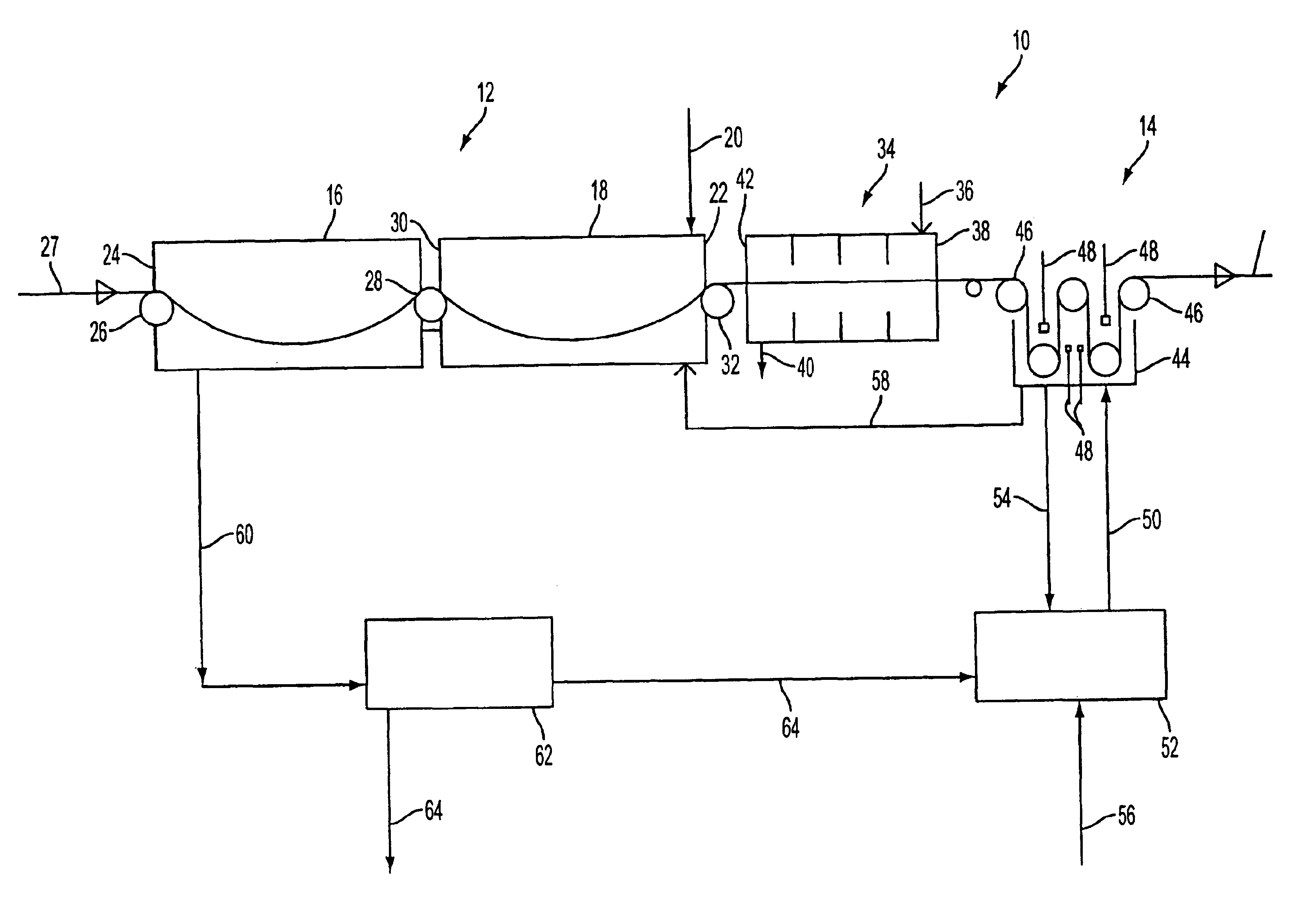
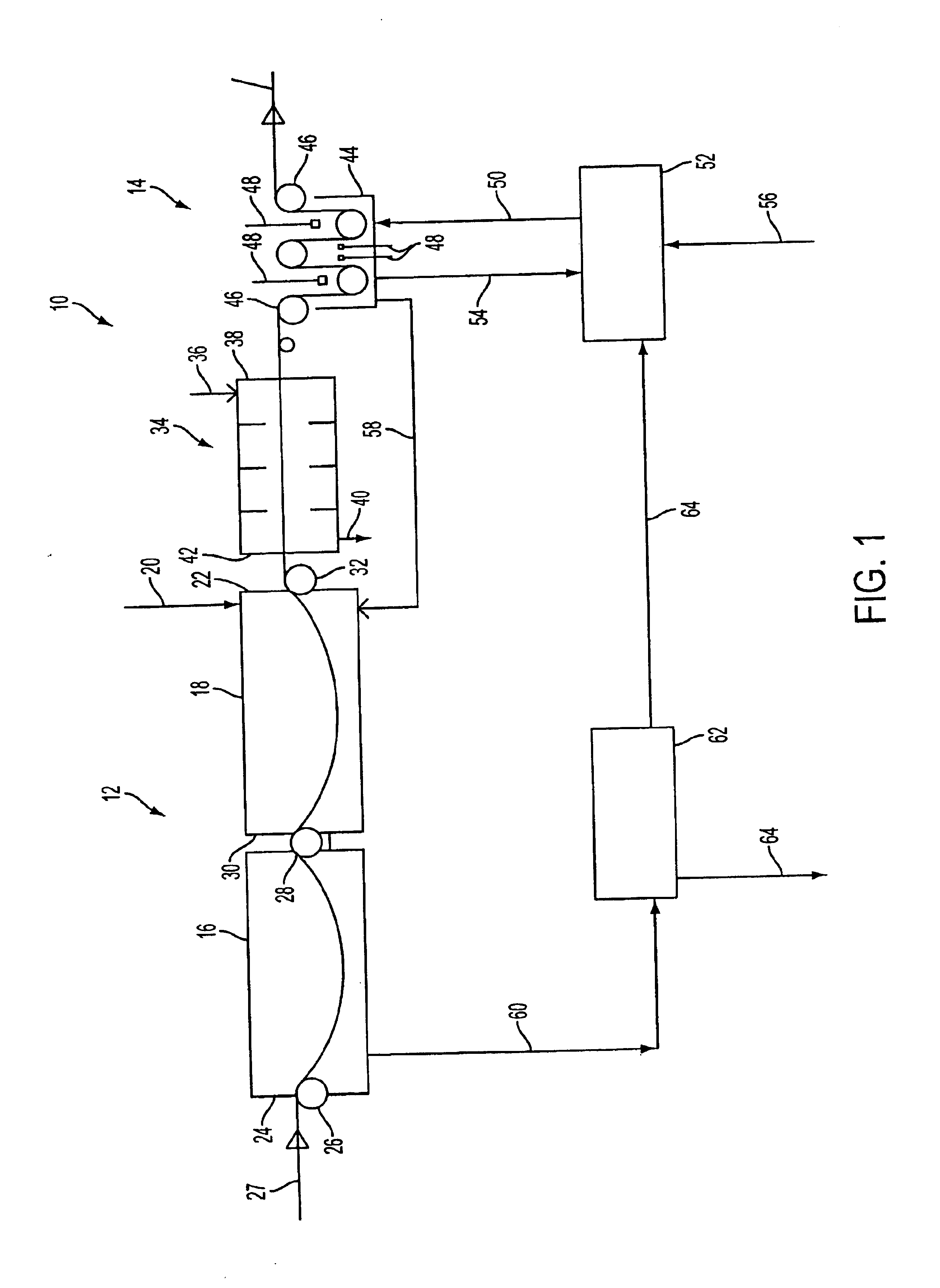
A sulfuric acid pickling solution containing 20% sulfuric acid at a temperature of 90° C. was supplied to the pickling tanks. A hot-rolled steel strip was fed to the inlet end of the pickling tank and carried through the sulfuric acid pickling solution and discharged through the outlet end of the pickling tank. The steel strip was rinsed briefly with water to remove residual pickling acid and iron sulfate on the steel strip. The steel strip was then carried directly to the electro-coating tank. Galvanic cells in the electro-coating tank were positioned in a vertical orientation and equipped with insoluble titanium anodes coated with iridium dioxide (IRO2). The cells contained a zinc sulfate electrolyte solution with a pH of 1.5 and a temperature of 55° C. Four anodes were positioned in the galvanic cells, with two anodes positioned on the upper and lower side of the steel strip. The anodes were supplied with a current of 300 amps. The steel strip was fed through the electro-coatings...

example 2

A hydrochloric acid pickling solution containing 16% hydrochloric acid at a temperature of 80° C. was supplied to the pickling tank. The hot-rolled steel strip was passed through the pickling tank and supplied directly to the electrolytic coating tank without prior rinsing. The galvanic cells in the electro-coating tank were fitted with soluble zinc anodes in the form of strips. The electrolyte solution was a zinc chloride solution with a pH of 3.0 and a soluble iron content of approximately 5 grams per liter. An electric current was supplied to the anodes and the steel strip to form a layer of pure zinc on the steel strip. The coating was analyzed as being substantially pure zinc which produced a bright finish. The surface produced in this example was brighter than the zinc coating produced from the zinc sulfate electrolyte solution of Example 1. The resulting coating was assessed as adhering very well to the steel strip. Metallo-graphic investigations also showed that the pickling...

example 3

In this example, a hydrochloric acid pickling solution containing 16% concentration hydrochloric acid and a temperature of 80° C. was supplied to the pickling tank. The hot-rolled steel strip was directed through the pickling acid and supplied directly to the electro-coating tank. The spent pickling acid was withdrawn from the pickling tank and pumped to a dissolving column containing granulated zinc. The spent pickling acid withdrawn from the pickling tank contained 100 grams per liter iron, 60 grams per liter HCl and total chlorides of 190 grams per liter. The spent pickling acid effectively consumed the granulated zinc and provided an electrolyte solution containing 100 grams per liter iron, 54 grams per liter zinc and total chlorides of 190 grams per liter. This electrolyte solution was then carried to the electro-coating tank. The electro-coating tank was fitted with insoluble anodes and a diaphragm. An electric current was supplied to the anodes and the steel strip to form a l...


PUM

PropertyMeasurementUnit
Currentaaaaaaaaaa
Solutionaaaaaaaaaa

Abstract

A process and apparatus are provided for producing an electrolytically coated, hot-rolled steel strip without any intervening strips. The apparatus includes a chemical pickling section being combined in one line with an electrolytic coating section containing electrolytic cells so that the pickled steel strip is fed directly to the electrolytic coating section without any intermediate steps. The spent electrolyte solution from the electrocoating section to the pickling section to pickle the steel. The spent pickling acid can also be used to generate the electrolyte solution that is fed to the electrocoating section.

Description

FIELD OF THE INVENTIONThe present invention is directed to a process and apparatus for electrolytically coating a hot rolled steel substrate. More particularly, the invention is directed to a continuous process and apparatus for pickling a hot rolled steel and electrolytically coating the steel without any intermediate process steps.BACKGROUND OF THE INVENTIONIn the manufacture of steel products, a coating is often applied to the finished product. The main objective is to protect the steel product against corrosion. Coatings containing zinc or zinc alloys cover by far the largest share of the market for this purpose. However, tin and chrome coatings also have significant share in the packing plate sector of the market.In continuous processes for coating a steel strip, two processes in particular have attained major importance, namely, hot galvanizing and electrolytic galvanizing or electrolytic coating. Hot galvanizing, also referred to as the hot-dip process, immerses a steel subst...

Claims


Application Information

Patent Timeline
IPC IPC(8): C25D7/06C25D5/36C25D21/16
CPCC25D5/36C25D21/16C25D7/0614
Inventor KARNER, WILHELM
Owner ANDRITZ PATENTVERW GES
Why Eureka
Try Eureka