Confocal imaging

Inactive Publication Date: 2005-01-04
AGILENT TECH INC
View PDF1 Cites 128 Cited by
  • Summary
  • Abstract
  • Description
  • Claims
  • Application Information

AI Technical Summary

Benefits of technology

[0021]A further object of the present invention is to increase the flexibility of confocal imaging by the use of image processing means. Typical confocal microscopes are hardware oriented, mainly optics and electronics, which do not lend themselves to programmability and flexibility of use. The present invention preferably uses an area array image sensor with signals from the sensor being captured or acquired by a processor. Digital acquisition of image signals in this way allows for greater programmability. For example, specific areas of interest can be measured instead of the entire field-of-view so as to reduce the confocal measurement time.
[0022]Yet another objective of the invention is

Problems solved by technology

There are drawbacks with each of these categories.
One of the primary drawbacks is that the techniques are highly dependent on the reflective nature of the object under inspection.
For example, when an object has specular surfaces, the triangulation imaging techniques which relies on true reflections will not work properly.
Furthermore, when an object is surrounded by tall components, it may cause occlusion in the triangulation imaging technique.
A drawback with the interferometry imaging technique is that the measurement results are wrapped in a 2π image space.
Effective measurement of objects with large st

Method used


Image

  • Confocal imaging
  • Confocal imaging
  • Confocal imaging

Examples


Embodiment Construction

view of a microlens and pinhole array for use in the confocal imaging system of FIG. 3.

[0029]FIG. 4(b) is a cross-sectional view A—A′ of the microlens and pinhole array of FIG. 4(a).

[0030]FIG. 5 shows an alternative design of the microlens and pinhole array for use in the confocal imaging system of FIG. 3.

[0031]FIG. 6 is an illustration showing the relationship between the image and the object space.

[0032]FIG. 7 shows a block diagram of the image sensor, processing and control modules in accordance with the present invention.

[0033]FIG. 8 is a flow chart showing the major steps of computing the 3D map of an object.

DESCRIPTION OF A SPECIFIC EMBODIMENT

[0034]Confocal Imaging System

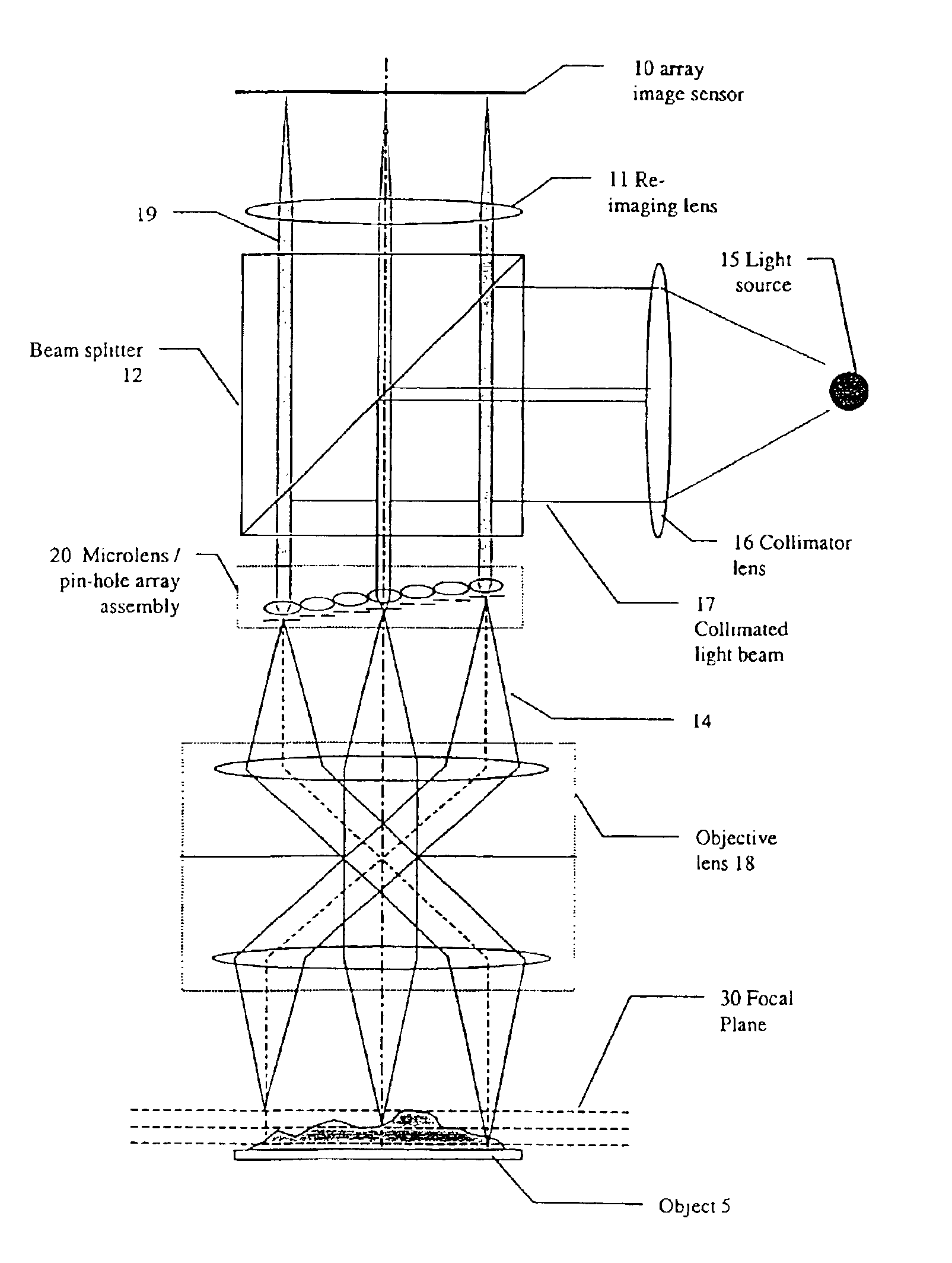
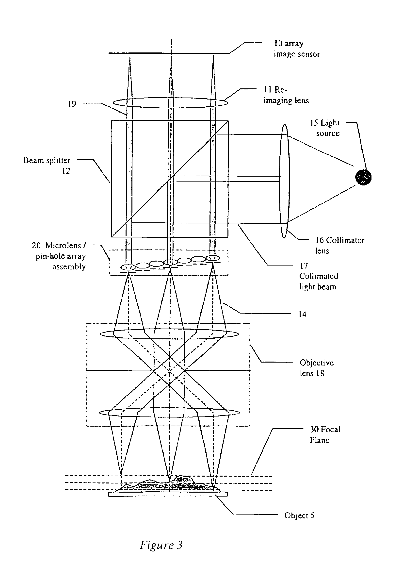
[0035]Referring to FIG. 3, there is shown a confocal imaging system for inspecting an object 5 to determine the three dimensional surface structure of the object. The confocal imaging system comprises a light source 15, and a collimator lens 16 for refracting light from the light source into a collimated light...


PUM


Abstract

A confocal imaging system for imaging a surface. The system includes an area array sensor having rows of sensors for detecting light reflected from the surface, and an optical system arranged to focus light from different focal planes on the surface to different sensor rows of the area array sensor.

Description

[0002]This invention relates to a system for high speed and high resolution confocal imaging for three dimensional measurement.BACKGROUND[0003]The measurement of three dimensional features on a surface has many applications. One particular example is in the inspection of electronic components and electronic component assemblies.[0004]The most common three dimensional inspection techniques available are optical techniques. These optical inspection techniques fall into several categories, including for example, structured light imaging, interferometry imaging, and triangulation imaging. There are drawbacks with each of these categories. One of the primary drawbacks is that the techniques are highly dependent on the reflective nature of the object under inspection. For example, when an object has specular surfaces, the triangulation imaging techniques which relies on true reflections will not work properly. Furthermore, when an object is surrounded by tall components, it may cause occl...

Claims


Application Information

Patent Timeline
IPC IPC(8): G02B21/00
CPCG02B21/0024G02B21/008G02B21/004
Inventor TOH, PENG SENG
Owner AGILENT TECH INC
Why Eureka
Try Eureka