Method for reducing coefficient of thermal expansion in chip attach packages

a technology of thermal expansion and chip, applied in the field of method for reducing the coefficient of thermal expansion in the chip, can solve the problems of warpage within the package, chip cracking, and often expensive process steps, and achieve the effects of lowering the cte, lowering the cte, and lowering the

Inactive Publication Date: 2005-01-11
IBM CORP
View PDF9 Cites 5 Cited by
  • Summary
  • Abstract
  • Description
  • Claims
  • Application Information

AI Technical Summary

Benefits of technology

A particular advantage of the present invention is that the non-woven mat can be incorporated during the assembly of an otherwise conventional laminate, to lower the CTE of the laminate. Thus, conventional laminates which have already been designed for use in a particular circuitized structure or use in a particular manufacturing line, do not have to be redesigned, or reengineered in order to lower the CTE, as would be necessitated with other methods of lowering the CTE in the laminate.
is that the non-woven mat can be incorporated during the assembly of an otherwise conventional laminate, to lower the CTE of the laminate. Thus, conventional laminates which have already been designed for use in a particular circuitized structure or use in a particular manufacturing line, do not have to be redesigned, or reengineered in order to lower the CTE, as would be necessitated with other methods of lowering the CTE in the laminate.
A further advantage of the present reduced CTE laminate is that additional resin need not be employed beyond the amount used in conventional laminates. In addition, the overall thickness of the reduced CTE laminate is not increased significantly, and thus the thickness of packages which comprise the reduced CTE laminate are not increased significantly.
The CTE of the reduced CTE laminate is adjusted as desired, preferably by varying the weight, density, or the number of plies of the non-woven mat employed. To lower the CTE of a laminate, the “amount” of the non-woven mat is determined based on the amount of glass cloth and the amount of resin to be present in the laminate.
In one embodiment of the invention, the CTE of the reduced CTE laminate is determined according to the following formula, designated “formula A”, a weighted average for determining VOL and / or CTE: CTEcomp /  ⁢CORE=(CTER)⁢(MODR)⁢(VOLR)+(CTEG)⁢(MODG)⁢(VOLG)+(CTEC)⁢(MODC)⁢(VOLC)+(CTEQ)⁢(MODQ)⁢(VOLQ)(MODR)⁢(VOLR)+(MODG)⁢(VOLG)+(MODC)⁢(VOLC)+(MODQ)⁢(VOLQ)
where:CTER=CTE of the resin,MODR=modulus of resin,VOLR=Volume fraction of resin,CTEG=CTE of woven glass cloth,MODG=Modulus of woven glass cloth,VOLG=Volume fraction of glass cloth,CTEC=CTE of copper,MODC=Modulus of copper,VOLC=Volume of fraction of copper,CTEQ=CTE of mat fiber, quartz,MODQ=Modulus of mat fiber, quartz,VOLQ=Volume fraction of fiber mat.

Problems solved by technology

The differential expansion can cause warpage within these packages, including flip chip attach packages.
This warpage can fatigue chip attach joints and also cause chip cracking.
Attempts have been made to reduce the warpage of the package; however they require additional, often expensive process steps.
Copper-invar-copper is expensive and difficult to drill.
Molybdenum is expensive, tough to drill, and hard to etch with conventional etchants.
However, encapsulants and top stiffeners add extra processing steps, cost, complexity and they occupy additional space.
However, dielectric which employs woven quartz cloth is thick and heavy which limits the usefulness of the prepreg.
Furthermore, laminates made with such quartz prepreg are difficult to drill due to the hardness of the quartz and the thickness of the quartz yarn bundles.

Method used


Image

  • Method for reducing coefficient of thermal expansion in chip attach packages
  • Method for reducing coefficient of thermal expansion in chip attach packages
  • Method for reducing coefficient of thermal expansion in chip attach packages

Examples


example 1

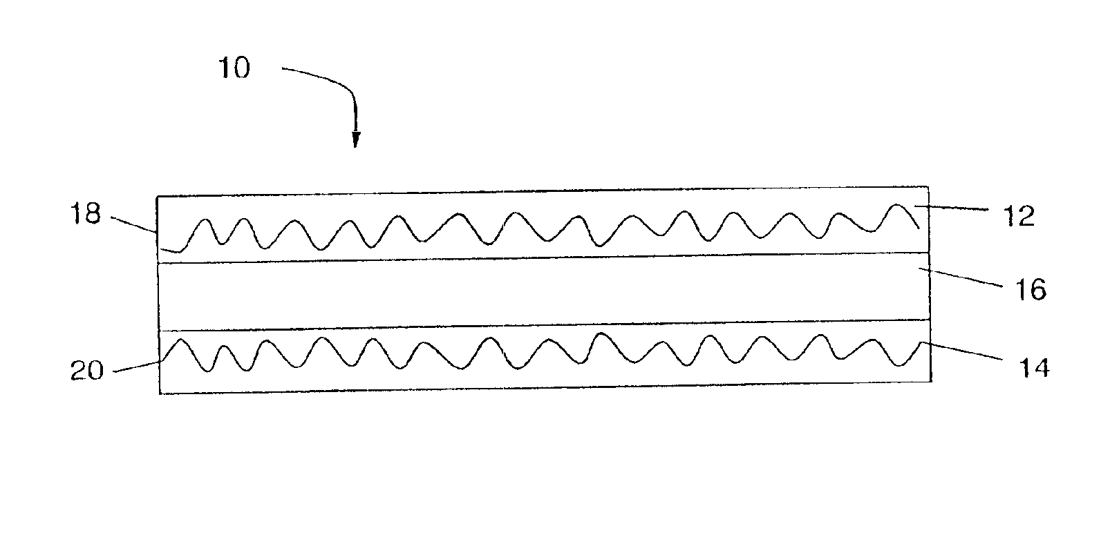
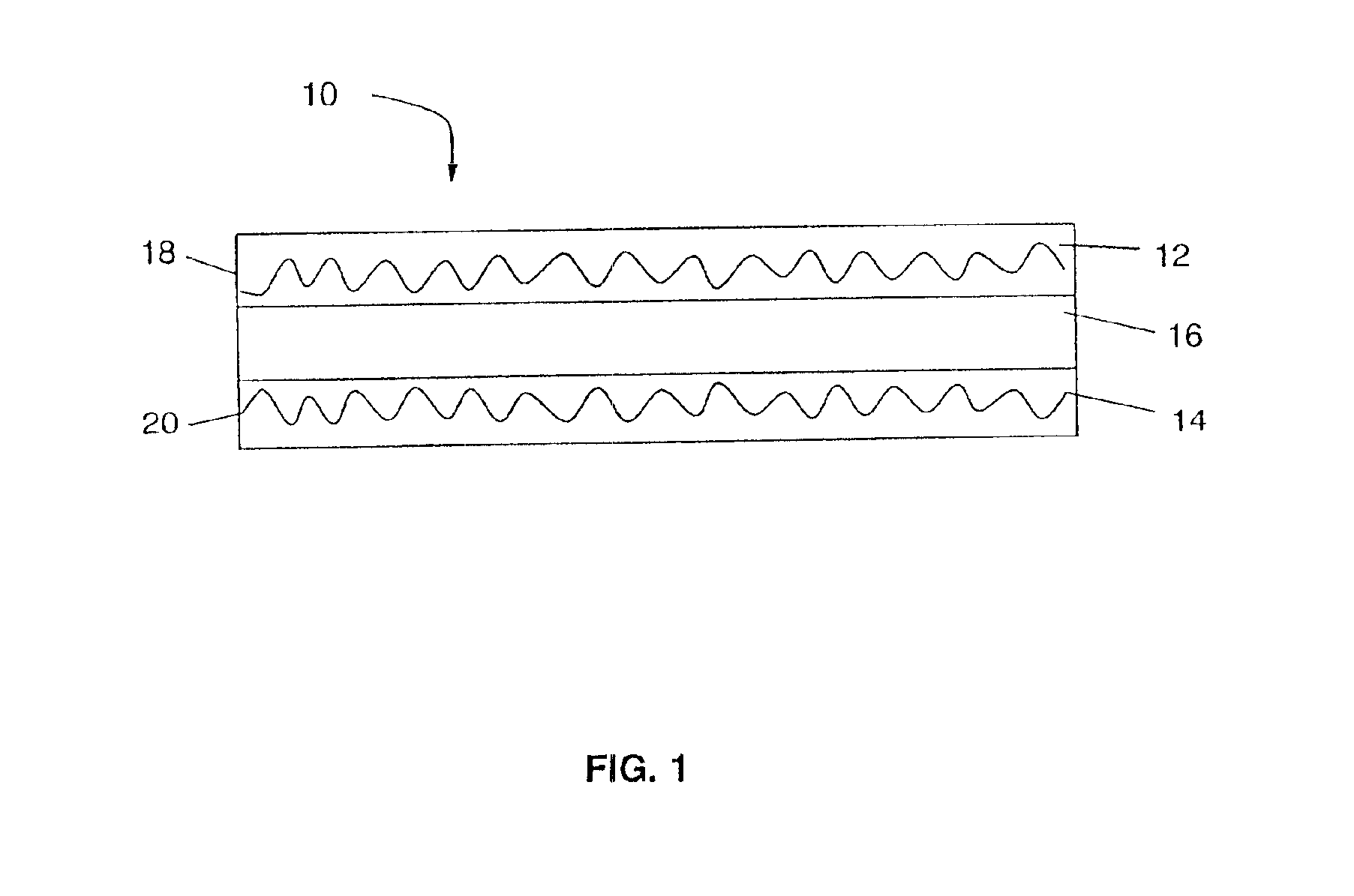
Prepreg was fabricated to provide a prepreg having about 60% by weight epoxy resin, 0.1% by weight curing accelerator 2-methyl imidizole and 40% by weight E-glass 1080, and b-stage cured to about 20 to 30%. Next, a multilayered structure was assembled which comprised a layer of copper sheet, a first layer of prepreg atop the copper, a second layer of prepreg atop the first layer of prepreg, a layer of non-woven quartz mat, a third and fourth layer of prepreg and finally a second layer of copper sheet. The non-woven quartz mat was about 0.004 inches thick before lamination, had a weight per unit area of about 17 g / m2 and was obtained from Technical Fiber Products Company. The multilayered structure was then vacuum laminated in a Wabash lamination press, at 185° C. for about 120 minutes at around 750 psi, to provide a reduced CTE laminate, in this case a laminate core. The copper layers on the outside of the core were then etched to form the circuit features using conventional techniq...

example 2

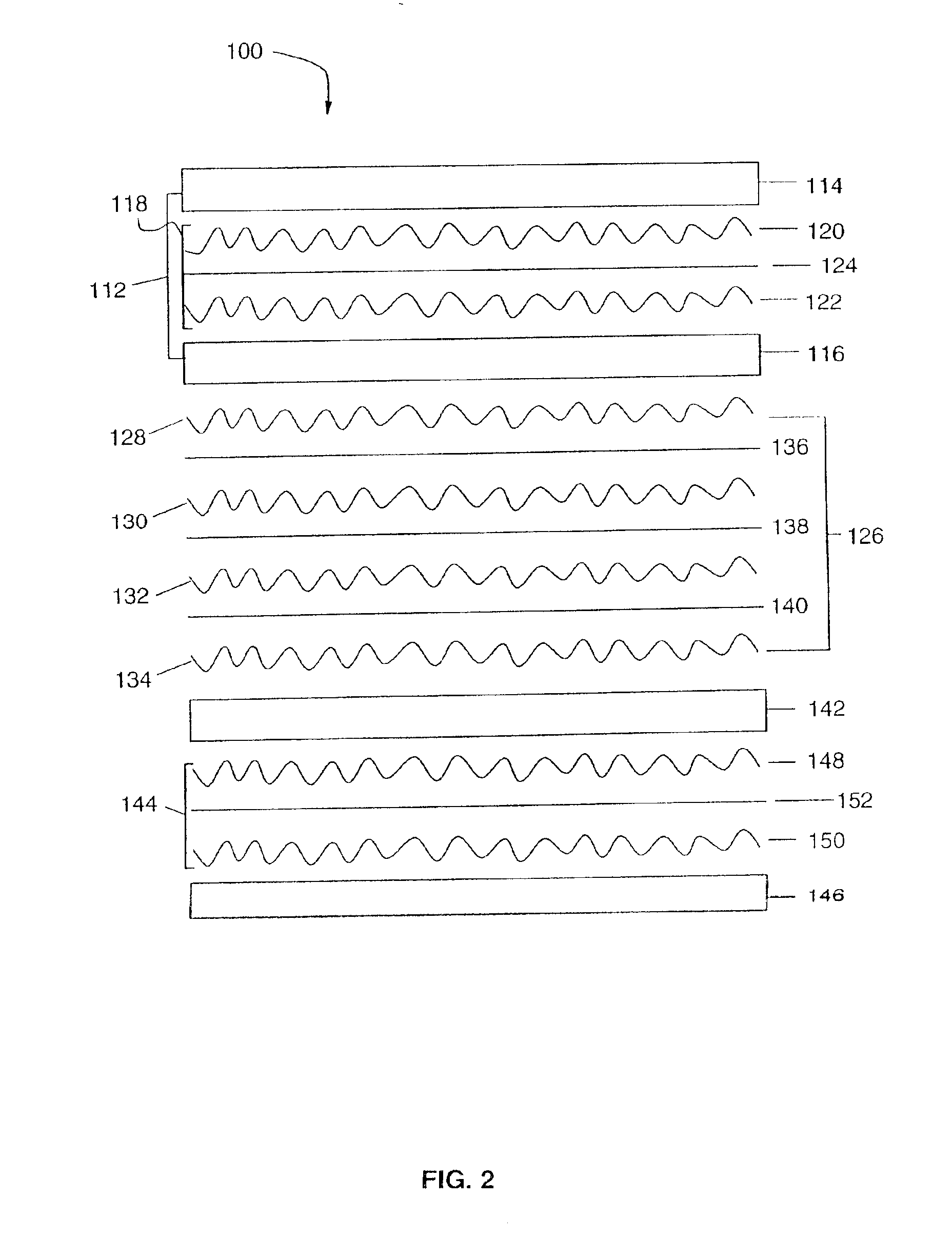
A reduced CTE laminate structure was made as in example 1, except that the core lacked a non-woven mat. Instead a non-woven quartz mat was employed between the fifth and sixth prepreg layers, and between the seventh and eight prepreg layers, so that 2.3% rather than 1.2% of the laminate structure was quartz non-woven mat. The resulting composite structure had a total thickness of about 26.2 mils.

example 3

A reduced CTE laminate structure was made as in example 1, except that a non-woven quartz mat was also employed between the fifth and sixth prepreg layers, and between the seventh and eight prepreg layers, so 3.4% rather than 1.2% of the laminate was quartz non-woven mat. The resulting laminate structure had a total thickness of about 26.5 mils.


PUM

PropertyMeasurementUnit
lengthaaaaaaaaaa
diameteraaaaaaaaaa
weight per unit areaaaaaaaaaaa

Abstract

A simple, inexpensive, drillable, reduced CTE laminate and circuitized structures comprising the reduced CTE laminate, is provided. One embodiment of the reduced CTE laminate comprises: from about 40% to 75%, preferably from about 55% to 65%, by weight resin; from about 0.05% to 0.3%, preferably from about 0.08% to 0.10%, by weight curing agent; from about 25% to 60%, preferably from about 30% to 40%, by weight, woven cloth; from about 1% to 15%, preferably from about 5% to 10%, by volume, non-woven quartz mat. The method for making reduced CTE laminate and laminate structures comprises the following steps: providing non-woven quartz mat; providing a prepreg, preferably B-stage cured to not more than about 40%, preferably not more than 30% of full cure; sandwiching the non-woven quartz mat between two layers of prepreg, and reflowing the resin of the prepreg into the quartz mat.

Description

The presence of different materials within a chip attach package, leads to different coefficients of thermal expansion within the package. The differential expansion can cause warpage within these packages, including flip chip attach packages. This warpage can fatigue chip attach joints and also cause chip cracking.Attempts have been made to reduce the warpage of the package; however they require additional, often expensive process steps. Material shaving a low coefficient of thermal expansion, like molybdenum, combinations of metals like copper-invar-copper, or other exotic organic reinforcements such as Kevlar, have been employed in packages to reduce the coefficient of thermal expansion. Kevlar, however, absorbs moisture. Copper-invar-copper is expensive and difficult to drill. Molybdenum is expensive, tough to drill, and hard to etch with conventional etchants.Attachments such as stiffeners or encapsulants on top of the chip are often employed to counteract warpage. However, enc...

Claims


Application Information

Patent Timeline
Patent Type & Authority Patents(United States)
IPC IPC(8): B32B5/28B32B5/22H05K1/03
CPCB32B5/28H05K1/036H05K1/0366Y10T29/4913H05K2201/0293H05K2201/068H05K2201/029Y10T442/3537Y10T442/3659Y10T442/3585Y10T442/2361Y10T442/3602Y10T442/2992Y10T442/3577Y10T442/3569B32B5/02B32B2260/023B32B5/26B32B2553/00B32B2262/101B32B2260/046B32B2305/20
Inventor BLUMBERG, LAWRENCE ROBERTJAPP, ROBERT MAYNARDRUDIK, WILLIAM JOHNSUROWKA, JOHN FRANK
Owner IBM CORP
Why Eureka
Try Eureka