
Pattern test device

a pattern test and test tube technology, applied in the direction of photomechanical treatment originals, semiconductor/solid-state device testing/measurement, instruments, etc., can solve the problems of large man-hours, large division costs, and reduce the throughput of the pattern test tube. , to achieve the effect of reducing man-hours and raising the throughput of judgemen

Inactive Publication Date: 2005-01-11
RENESAS ELECTRONICS CORP
View PDF9 Cites 14 Cited by
  • Summary
  • Abstract
  • Description
  • Claims
  • Application Information

AI Technical Summary

Benefits of technology

The present invention provides a pattern test device and method that can reduce man-hours and increase throughput by automatically setting sub-areas in a mask area based on design data and reference pattern data, and selecting thresholds for testing defects. The device and method can thus improve efficiency and accuracy in pattern testing.

Problems solved by technology

However, this is not noticed in the conventional technique, and a minor defect which has an insignificant influence on the resultant semiconductor device is also detected by the conventional technique.
This reduces the throughput of the pattern test device and raises a turn around time for fabricating the semiconductor device.
In the conventional technique described in the above publication, since the mask area must be divided into a large number of sub-areas beforehand, the division itself costs large man-hours.
In addition, the judgement section 78 or 80 must determine the threshold for comparison each time the pattern test advances crossing a boundary between the sub-areas, which complicates the control for the comparator in the pattern test device and thus reduces the throughput of the pattern test device.

Method used


Image

  • Pattern test device
  • Pattern test device
  • Pattern test device

Examples


Embodiment Construction

Now, the present invention is more specifically described with reference to accompanying drawings.

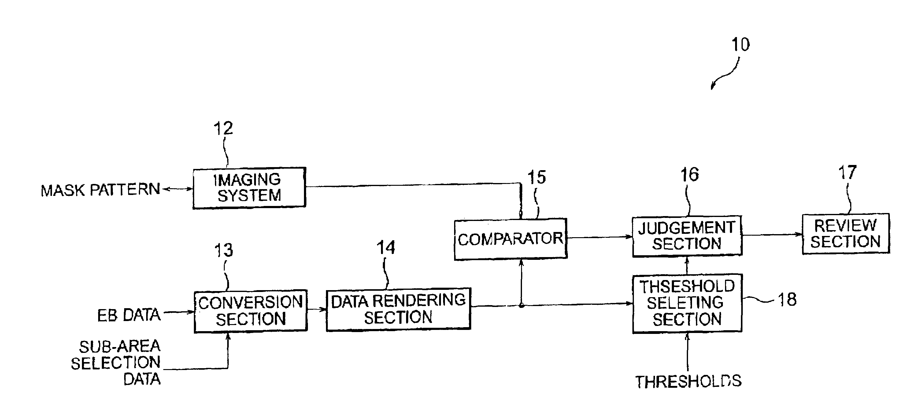
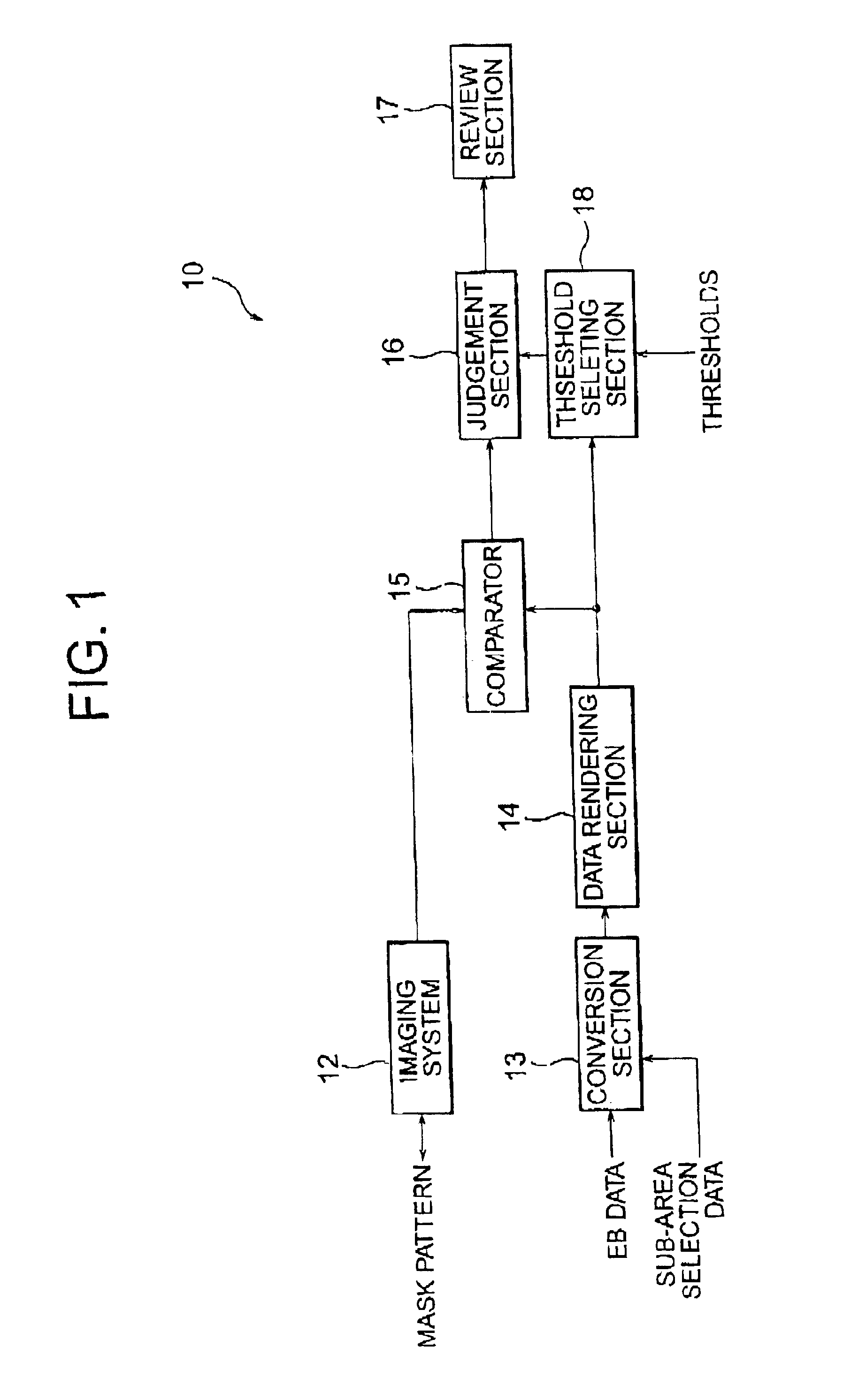
Referring to FIG. 1, a pattern test device, generally designated by numeral 10, according to a first embodiment of the present invention includes an imaging system 12, a conversion section (reference pattern generator) 13, a data rendering section 14, a comparator 15, a judgement section 16, a review section 17 and a threshold selecting section 18.

The imaging system 12 picks-up the image of a mask pattern (or reticle pattern) to generate test pattern data, and delivers the same to the comparator 15. The test pattern data includes a plurality of unit pixel data, each of which is encoded to have a gray scale level from 0 to 255 depending on the brightness, or gray scale level, of the unit pixel.

Referring to FIG. 4, the imaging system 12 includes a laser device 30, a half mirror 31, a transmission-beam optical system 32, a reflection-beam optical system 33 and a monitor optical system 34. ...


PUM

PropertyMeasurementUnit
thresholdaaaaaaaaaa
brightnessaaaaaaaaaa
optical imagingaaaaaaaaaa

Abstract

A pattern test device has a reference data generator for generating reference pattern data and setting a first sub-area or a second sub-area in a mask area depending on the accuracy for the pattern test. A threshold selecting section selects first or second threshold depending on the test location residing in the first sub-area or second sub-area, whereby the judgement section judges presence or absence of a defect in the mask area while using the first or second threshold to compare therewith difference data between the test pattern data and the reference pattern data.

Description

BACKGROUND OF THE INVENTION(a) Field of the InventionThe present invention relates to a pattern test device and, more particularly, to a pattern test device for detecting a defect in a test pattern data by comparing the test pattern data obtained by imaging a mask pattern against a reference pattern data. The present invention also relates to a pattern test method.(b) Description of the Related ArtA typical test method for detecting a defect in a mask pattern or reticle pattern (simply referred to as mask pattern in this text) uses a test pattern data obtained by imaging the mask pattern in a mask by using a CCD camera or optical imaging system, for example. The test pattern data are compared against corresponding reference pattern data or design data stored in a CAD system for electron beam writing.FIG. 5 shows an example of a conventional pattern test device. The pattern test device, generally designated by numeral 11, includes an imaging system 12, a conversion section 13, a comp...

Claims


Application Information

Patent Timeline
Patent Type & Authority Patents(United States)
IPC IPC(8): G01N21/956G01N21/88H01L23/544G01B11/30G03F1/84H01L21/66
CPCH01L22/34G01N21/95607G01N21/88
Inventor ANDO, AKIHIKO
Owner RENESAS ELECTRONICS CORP
Learn More