Environmental barrier coating

a barrier coating and environmental technology, applied in the direction of chemical vapor deposition coating, liquid fuel engine components, non-positive displacement fluid engines, etc., can solve the problems of unacceptably high recession rate for many component lifetime requirements, unacceptably high recession rate for extended component lifetime requirements

Inactive Publication Date: 2005-01-18
GENERAL ELECTRIC CO
View PDF28 Cites 53 Cited by
  • Summary
  • Abstract
  • Description
  • Claims
  • Application Information

AI Technical Summary

Problems solved by technology

However, the components are known to experience significant surface recession under exposure to high-temperature, aqueous environments.
This rate is unacceptably high for many component lifetime requirements.
However, after exposure to temperatures above about 1200° C. for long periods of time, the recession rate can be unacceptably high for extended component lifetime requirements.
Furthermore, chemical reactions occur which result in consumption of the bond coat and the intermediate coat, which may further reduce the component lifetime below the desired level.
As the reaction between the silica layer and the intermediate coat proceeds, the oxidation of the silicon bond coat increases, eventually consuming the bond coat and the intermediate coat.
The reaction products of the silica and intermediate coat are typically unstable and promote poor adherence between the bond coat and the intermediate coat.
The reaction products may be present in multiple phases and may possess other undesirable properties such as high thermal expansion mismatch with the bond coat and the intermediate coat.
Once the intermediate coat is consumed, further chemical reactions may occur between the top coat and any remaining bond coat, leading to further consumption of the bond coat.
Once the bond coat is consumed, the substrate is oxidized, leading to gas bubble formation and often spatling of the entire environmental barrier coating.
Absent the protection of the environmental barrier coating, the substrate is exposed, resulting in a high rate of recession of the substrate and curtailing component life.
These and other drawbacks are present in known systems and techniques.

Method used


Image

  • Environmental barrier coating
  • Environmental barrier coating
  • Environmental barrier coating

Examples


example

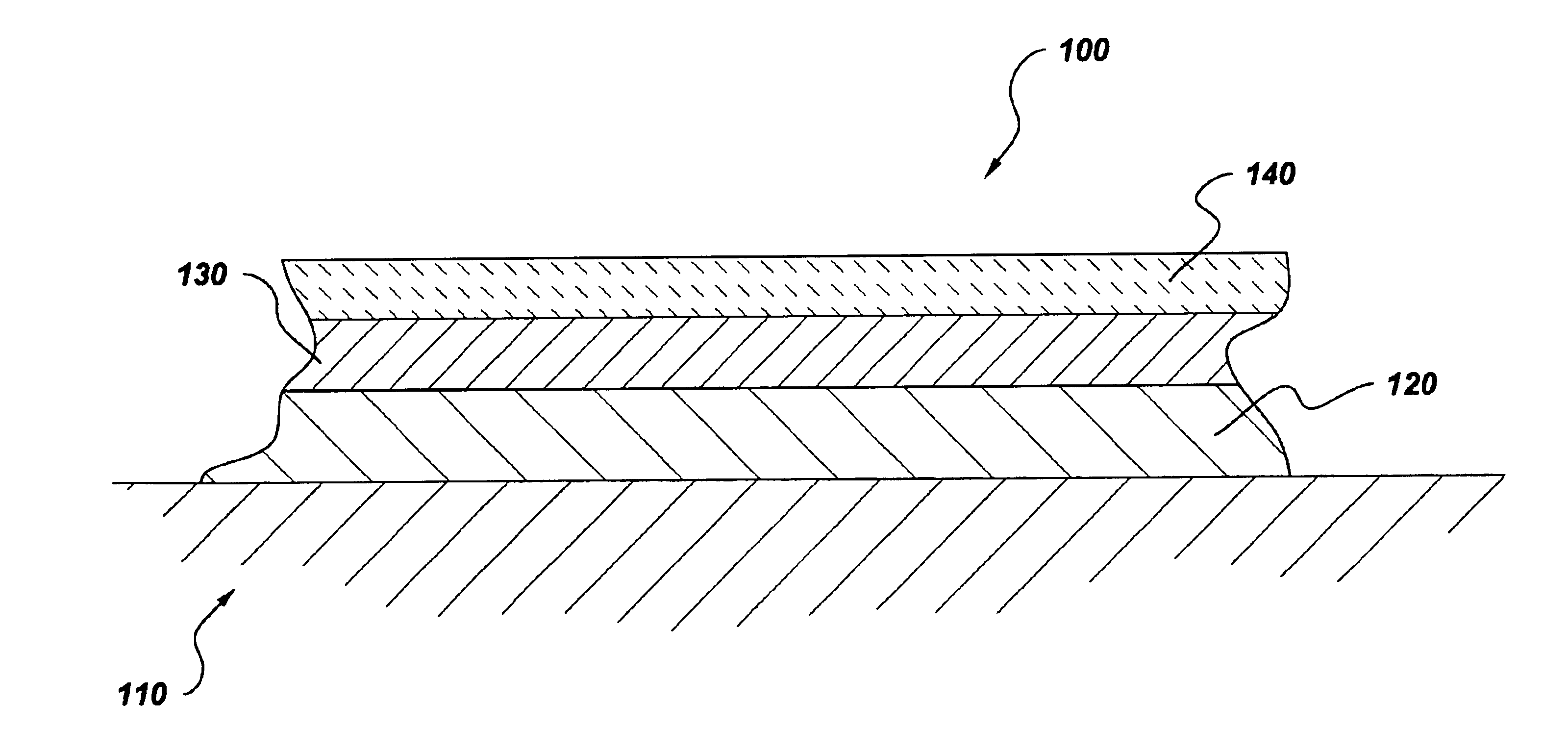
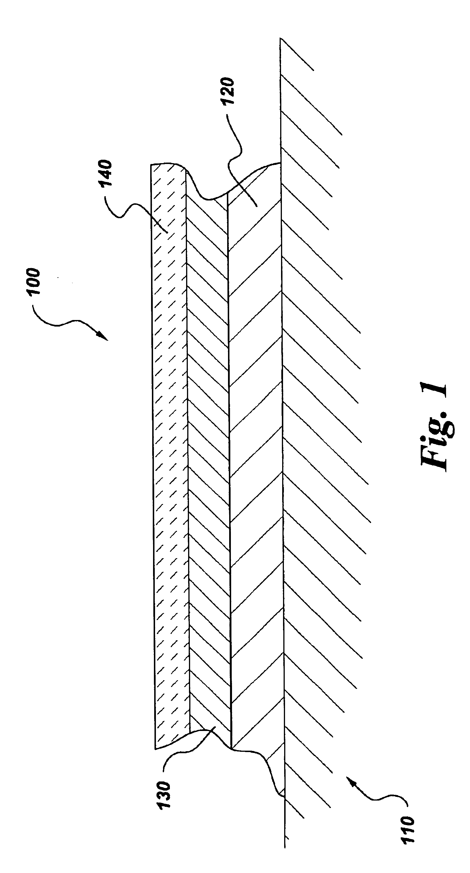
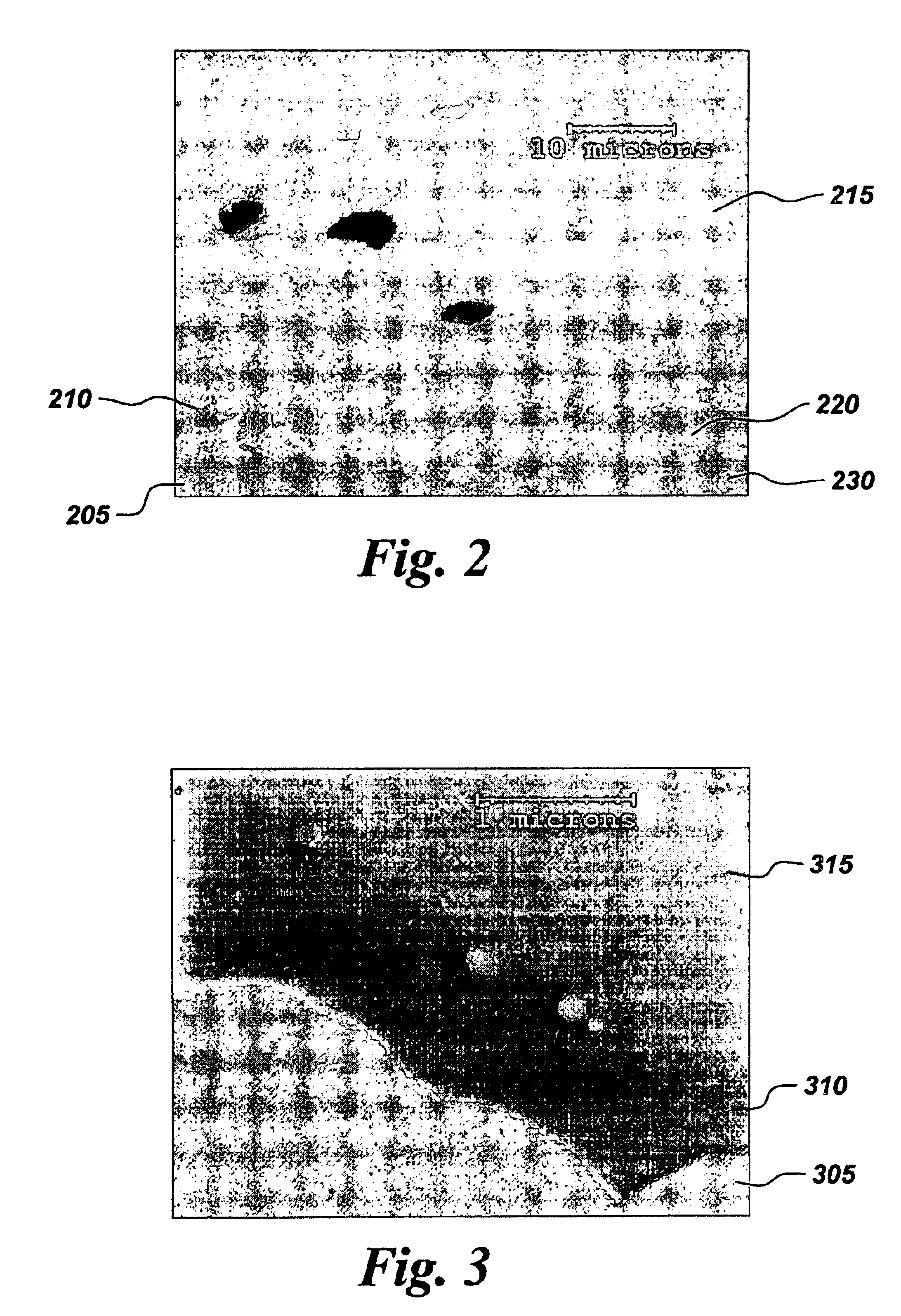
Sintered pellets of compositions corresponding to an intermediate coat having a composition in accordance with one aspect of the present invention (tantalum aluminate) and an intermediate coat having a conventional composition (barium strontium aluminosilicate or BSAS) were prepared and tested. These pellets were coated with silicon, such as may be found in an exemplary bond coat, and then exposed to an oxidative high temperature environment as might be experienced in a gas turbine engine, for example. The interface of the pellet and the silicon coating, corresponding to an interface of an intermediate coat and a bond coat, was then analyzed for each of the two pellet compositions.

Tantalum aluminate was prepared from a starting powder mixture of 50 mol % Ta2O5 and 50 mol % Al2O3. Both powders were 99.99% pure and had a −325 mesh particle size. The powders were obtained from Cerac, Inc. of Milwaukee, Wis. The Al2O3 and Ta2O5 powders were mixed with ethanol and zirconia milling media ...


PUM

PropertyMeasurementUnit
temperaturesaaaaaaaaaa
thicknessaaaaaaaaaa

Abstract

A coating for a silicon based material such as those used in high temperature environments. An aspect of the invention is directed to an environmental barrier coating including a silicon bond coat, and intermediate coat, and a top coat. The intermediate coat may comprise tantalum aluminate, niobium aluminate, or a mixture of the two. The intermediate coat is resistant to solid-state suburface reactions with the bond coat and the top coat and is substantially inert to reactions with silica at high temperatures.

Description

BACKGROUND OF THE INVENTIONThis invention relates generally to barrier coatings, and more particularly to barrier coatings for use in high temperature, aqueous environments.Ceramic materials containing silicon and alloys containing silicon have been proposed for structures used in high temperature applications, such as gas turbine engines, heat exchangers, internal combustion engines, and the like. These materials are particularly useful in gas turbine engines which operate at high temperatures in aqueous environments.The desired lifetime for components in such turbine applications may be tens of thousands of hours at temperatures above 1000° C., for example. However, the components are known to experience significant surface recession under exposure to high-temperature, aqueous environments. Volatile silicon-based gaseous species form at temperatures over about 1000° C. which causes the surface of the components to recede. The rate of recession may be 0.254 mm (0.010 in) or greater...

Claims


Application Information

Patent Timeline
Patent Type & Authority Patents(United States)
IPC IPC(8): B32B9/04C04B41/89C23C16/06C23C4/10C23C28/04F01D5/28F03B3/12F03B3/00F02C7/00C04B41/52C23C28/00
CPCC04B41/009C04B41/52C04B41/89C23C28/04C04B41/4527C04B41/5096C04B41/5035C04B41/5032C04B41/5051C04B41/522C04B41/5027C04B41/5024C04B35/565C04B35/584C04B35/806C04B35/597F05B2230/90F05C2253/12Y02T50/67Y02T50/60
Inventor SAAK, JENNIFER SUMESCHTER, PETER JOELMITCHELL, DAVID JOSEPHLUTHRA, KRISHAN LAL
Owner GENERAL ELECTRIC CO
Why Eureka
Try Eureka