Radiolucent bone graft

Inactive Publication Date: 2005-01-25
CTL MEDICAL CORP +1
View PDF8 Cites 135 Cited by
  • Summary
  • Abstract
  • Description
  • Claims
  • Application Information

AI Technical Summary

Benefits of technology

Further alternative bone graft configurations may include controlled porosity gradations to define a relatively low porosity first region or regions substantially emulating cortical bone, to define a high strength loading bearing zone or strut for absorbing impaction and insertion load, in combination with one or more relatively high porosity second regions substantially emulating cancellous bone for contacting adjacent patient bone for enhanced bone ingrowth and fusion.
The resultant bone graft exhib

Problems solved by technology

However, titanium-based implant devices exhibit poor radiolucency characteristics, presenting difficulties in post-operative monitoring and evaluation of the fusion process due to the radio-shadow produced by the non-lucent metal.
Moreover, titanium-based implant devices are primarily load bearing but are not osteoconductive, i.e., not conducive to direct and strong mechanical attachment to patient bone tissue, leading to potential graft necrosis, poor fusion and stability.
Further, they suffer from poor pull out strength resulting in poor stability, primarily due to the limited options in machining the contact surfaces.
Allograft bone implants also have variable materials properties and, perhaps most important of all, are in very limited supply.
In response to these problems some developers are attempting to use porous tantalum-based metal constructs, but these have met with limited success owing to the poor elastic modulii of porous metals.
However, the titanium-based structure can form a thin fibrous

Method used


Image

  • Radiolucent bone graft
  • Radiolucent bone graft
  • Radiolucent bone graft

Examples


Embodiment Construction

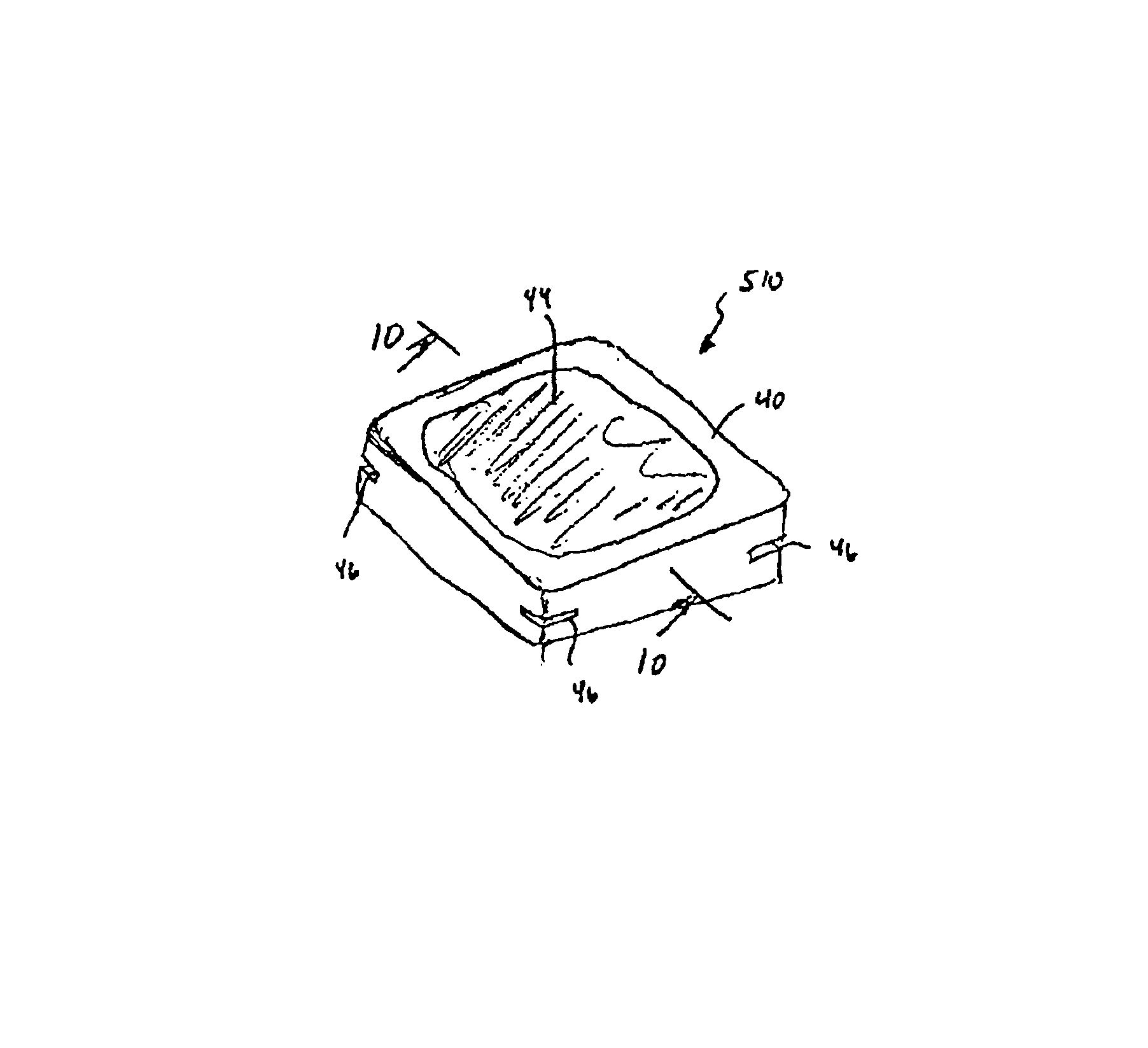
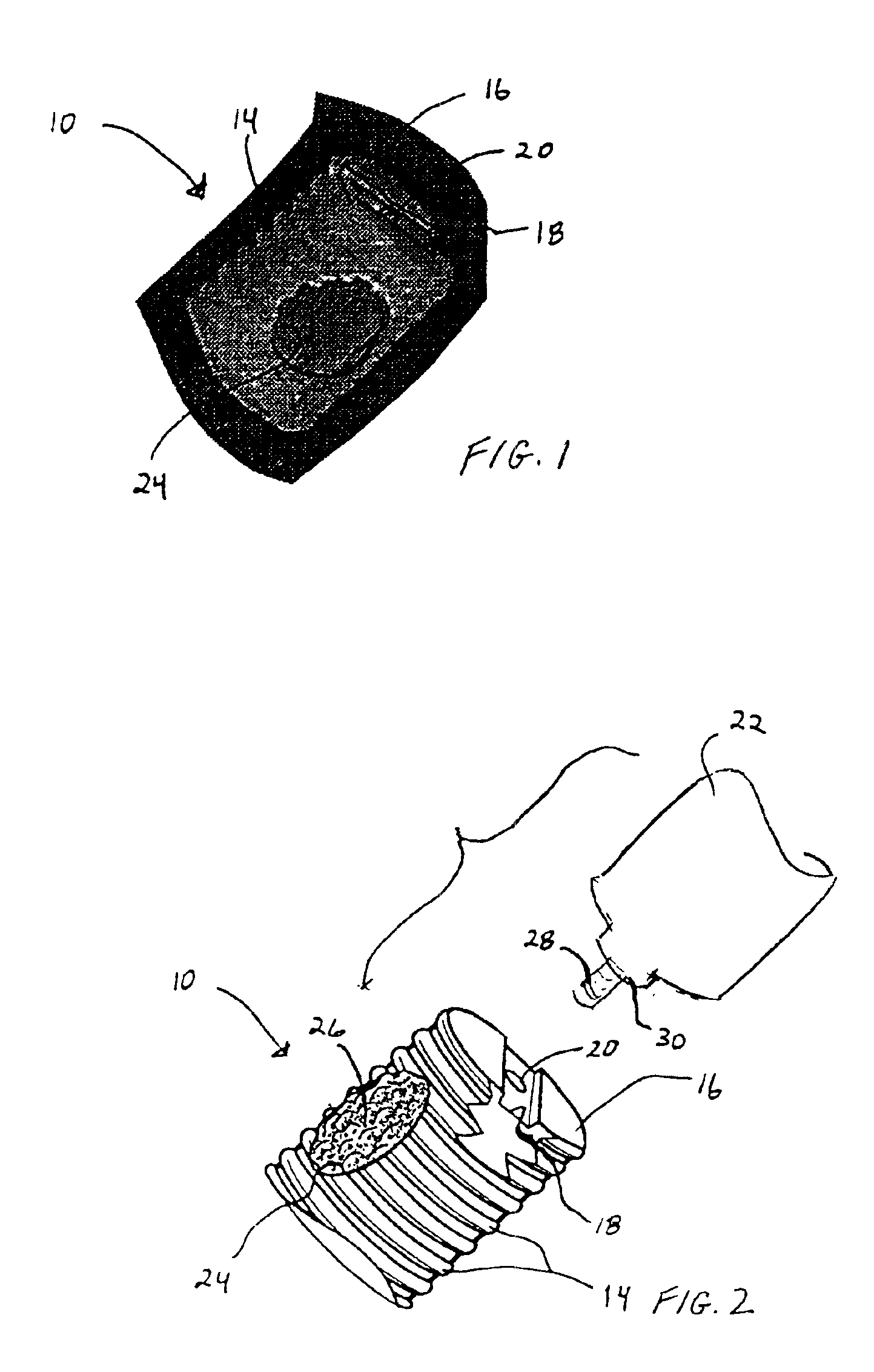
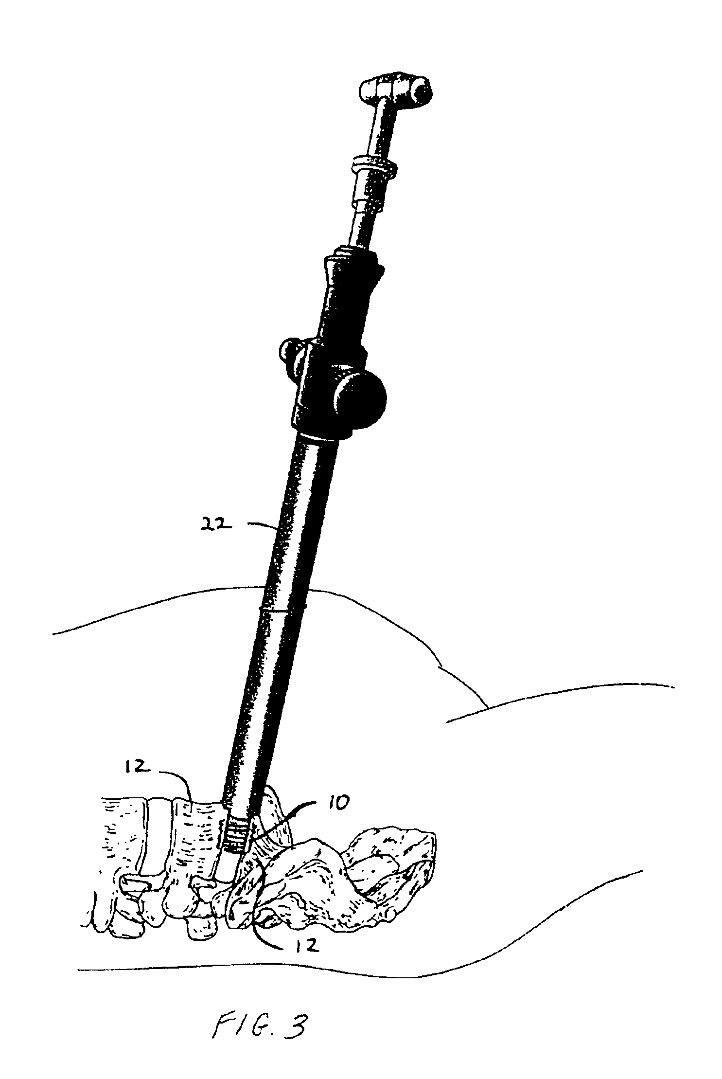
As shown in the exemplary drawings, a radiolucent bone graft such as a spinal fusion cage referred to generally in FIGS. 1-3 by the reference numeral 10 is provided for seated implantation between a pair of adjacent patient bones such as spinal vertebrae 12 (FIG. 3) to maintain the vertebrae in spaced relation while promoting interbody bone ingrowth and fusion. In general, the improved bone graft 10 comprises a bio-compatible ceramic substrate having a porous construction to define an open lattice conducive to interbody bone ingrowth and fusion, while providing a strong mechanical load bearing structure analogous to the load bearing properties of cortical and cancellous bone. This open-celled ceramic substrate is coated internally and externally with a bio-active surface coating selected for relatively strong osteoconductive and osteoinductive properties, whereby the coated ceramic substrate provides a scaffold conducive to cell attachment and proliferation to promote interbody bone...


PUM

PropertyMeasurementUnit
Fractionaaaaaaaaaa
Fractionaaaaaaaaaa
Pore sizeaaaaaaaaaa

Abstract

An improved ceramic bone graft is provided for human implantation, particularly such as a spinal fusion cage for implantation into the inter-vertebral space between two adjacent vertebrae. The improved spinal fusion cage includes a substrate block of high strength ceramic having a selected size and shape to fit the anatomical space, and a controlled porosity analogous to natural bone. The substrate block is coated with a bio-active surface coating material such as hydroxyapatite or a calcium phosphate to promote bone ingrowth and enhanced bone fusion. Upon implantation, the fusion cage provides a spacer element having a desired combination of mechanical strength together with osteoconductivity and osteoinductivity to promote bone ingrowth and fusion, as well as radiolucency for facilitated post-operative monitoring. The fusion cage may additionally carry one or more natural or synthetic therapeutic agents for further promoting bone ingrowth and fusion.

Description

BACKGROUND OF THE INVENTIONThis invention relates generally to improvements in bone grafts such as spinal fusion cages of the type designed for human implantation between adjacent spinal vertebrae, to maintain the vertebrae in substantially fixed spaced relation while promoting interbody bone ingrowth and fusion therebetween. More particularly, this invention relates to an implantable bone graft such as a spinal fusion cage having an improved combination of enhanced mechanical strength together with osteoinductive and osteoconductive properties, in a ceramic-based device that additionally and beneficially provides radiolucency for facilitated post-operative monitoring.Implantable interbody bone grafts such as spinal fusion devices are known in the art and are routinely used by spine surgeons to keep adjacent vertebrae in a desired spaced-apart relation while interbody bone ingrowth and fusion takes place. Such spinal fusion devices are also used to provide weight bearing support bet...

Claims


Application Information

Patent Timeline
IPC IPC(8): A61F2/30A61F2/44A61F2/46A61L27/32A61L27/38A61L27/00A61L27/10A61L27/56A61L27/30A61F2/00A61F2/28
CPCA61F2/30767A61F2/446A61F2/447A61F2/4611A61L27/10A61L27/30A61L27/32A61L27/3608A61L27/365A61L27/3804A61L27/3847A61L27/56A61F2/442A61F2002/2835A61F2002/30011A61F2002/30016A61F2002/30064A61F2002/30153A61F2002/30158A61F2002/30166A61F2002/30179A61F2002/30224A61F2002/30235A61F2002/30261A61F2002/30266A61F2002/30271A61F2002/3028A61F2002/30329A61F2002/30616A61F2002/30677A61F2002/30733A61F2002/30774A61F2002/30777A61F2002/30789A61F2002/3082A61F2002/30822A61F2002/30827A61F2002/3085A61F2002/30881A61F2002/30891A61F2002/30892A61F2002/30896A61F2002/3092A61F2002/30968A61F2002/4475A61F2002/4623A61F2002/4627A61F2002/4629A61F2002/4648A61F2220/0025A61F2230/0019A61F2230/0026A61F2230/0028A61F2230/0058A61F2230/0063A61F2230/0069A61F2230/0082A61F2250/0019A61F2250/0023A61F2310/00203A61F2310/00239A61F2310/00796A61F2310/00928A61F2310/0097A61F2310/00976A61L2430/02A61L2430/38A61F2002/30593A61F2/4603A61L27/3834
Inventor KHANDKAR, ASHOK C.RAO, MAHENDRA S.
Owner CTL MEDICAL CORP
Why Eureka
Try Eureka