Osteoconductive spinal fixation system

a spinal fixation system and conductive technology, applied in the field of osteoconductive spinal fixation system, can solve the problems of fixation device, difficulty in post-operative monitoring and evaluation of the fusion process, extreme and debilitating pain of patients with such conditions, etc., and achieve the effect of high strength, high strength and high strength for spinal loading

Inactive Publication Date: 2006-12-07
AMEDICA A DELAWARE
View PDF19 Cites 100 Cited by
  • Summary
  • Abstract
  • Description
  • Claims
  • Application Information

AI Technical Summary

Benefits of technology

[0018] The thus-formed fixation device can be made in a variety of shapes and sizes to suit different specific implantation requirements. Preferred shapes include a rod or plate with a lordotic curvature. This rod has a dense inner cylinder of high strength for supporting spinal loading. The dense inner cylinder is surrounded along its axis by a structure of open porosity. The plate component is made of a dense body of high strength for receiving the screws and supporting load. The face of the plate which lies adjacent to the vertebral body is covered with a structure of open porosity. In turn, the porous structure has osteoconductive materials coating throughout the pores. This preferred embodiment aids in the fusion along the rod or plate, which is placed between transverse processes or adjacent to the interbody space. Additional preferred shapes include that of a bone screw. The bone screw is comprised of a dense substrate of high strength for spinal loading. Portions of the threaded shank of the screw are surrounding by a structure of open porosity. In turn, the porous structure has osteoconductive materials coating throughout the pores. This enables bone growth into the screw itself, thereby aiding in the fixation of the device to the vertebral body.
[0019] The resultant spinal fixation device exhibits relatively high mechanical strength for load bearing support, while additionally and desirably providing high osteoconductive and osteoinductive properties to achieve enhanced bone ingrowth and fusion. Importantly, these desirable characteristics are achieved in a structure which is substantially radiolucent so that the implant does not interfere with post-operative radiographic monitoring of the fusion process.

Problems solved by technology

Patients that suffer from such conditions usually experience extreme and debilitating pain as well as diminished nerve function.
However, as will be set forth in more detail below, there are some disadvantages associated with current fixation devices.
However, traditional titanium-based implant devices exhibit radio-opaque characteristics, presenting difficulties in post-operative monitoring and evaluation of the fusion process using x-ray or fluoroscopic imaging.
Radio-opacity presents a problem in that it does not allow structures located between the device and the imaging machine to be seen.
Additionally, metallic implants cause scattering, or shadowing, and distortion of MRI's and CT's.
These poor radiolucent properties can make it difficult, if not impossible to assess the bone growth using traditional means.
In some cases, surgeons must use costly thin slice CT reconstruction to analyze the new bone growth.
This is especially a problem for characterizing the bone growth between the transverse processes and in the interbody space, due to the titanium rod or plate being directly adjacent to the fusion material.
Moreover, traditional titanium-based implant devices are primarily load bearing but are not osteoconductive, i.e., not conducive to direct and strong mechanical attachment to patient bone tissue, leading to potential micro-motion between the implant and the host bone, causing possible poor fusion, instability and bone resorption.
However these devices have issues which make them difficult to use.
One such problem is a lack of load bearing strength, which might lead to failure of the implant after surgery.
Another issue is with intraoperative placement of the device, and postoperative radiographic analysis.
However, this radiotransparency makes it extremely difficult for the surgeon to know where the device is located, both during and after implantation.
Some devices utilize a radiographic marker to aid in this assessment, but exact location and orientation of the markers within the device still make it difficult for accurate assessment.
However, supply of autologous bone material is limited and significant complications are known to occur from bone harvesting.
Moreover, the costs associated with harvesting autograft bone material are high, requiring two separate incisions, with the patient having to undergo more pain and recuperation due to the harvesting and implantation processes.
Additionally, blood supply to the posterior lateral portion of the spine is generally low, meaning there is a lack of natural osteoinductive cells and growth factors, making it difficult to sustain bone growth in the area.
This can cause pseudoarthrosis, which may lead to loosening or breakage of the implant and result in patient pain.
It is also difficult to keep the autologous cancellous bone material in the proper placement between the transverse processes.
However, while these ceramic materials may provide satisfactory osteoconductive and bio-active properties, they have not provided the mechanical strength necessary for the implant.

Method used


Image

  • Osteoconductive spinal fixation system
  • Osteoconductive spinal fixation system
  • Osteoconductive spinal fixation system

Examples


Embodiment Construction

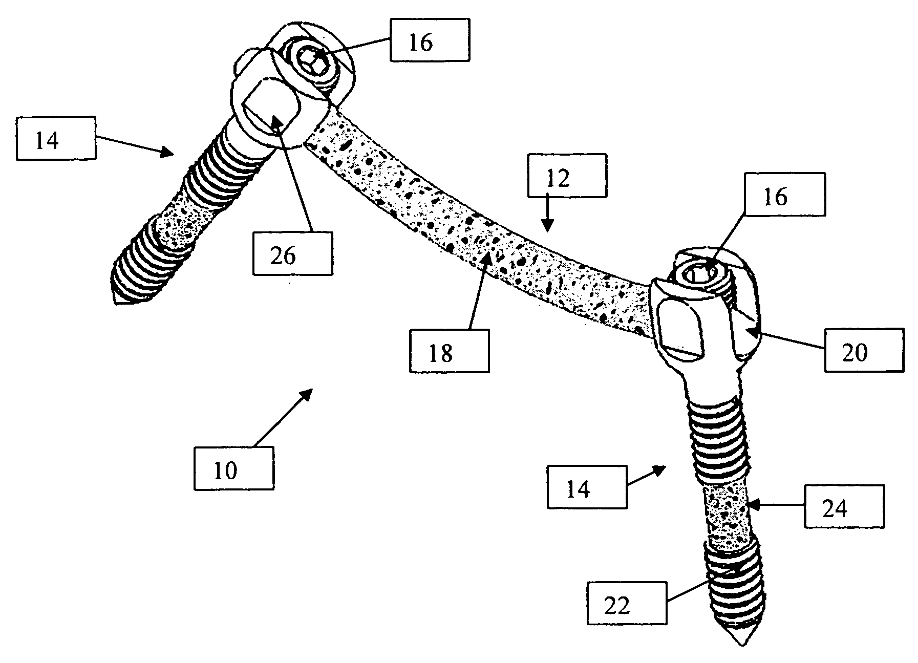
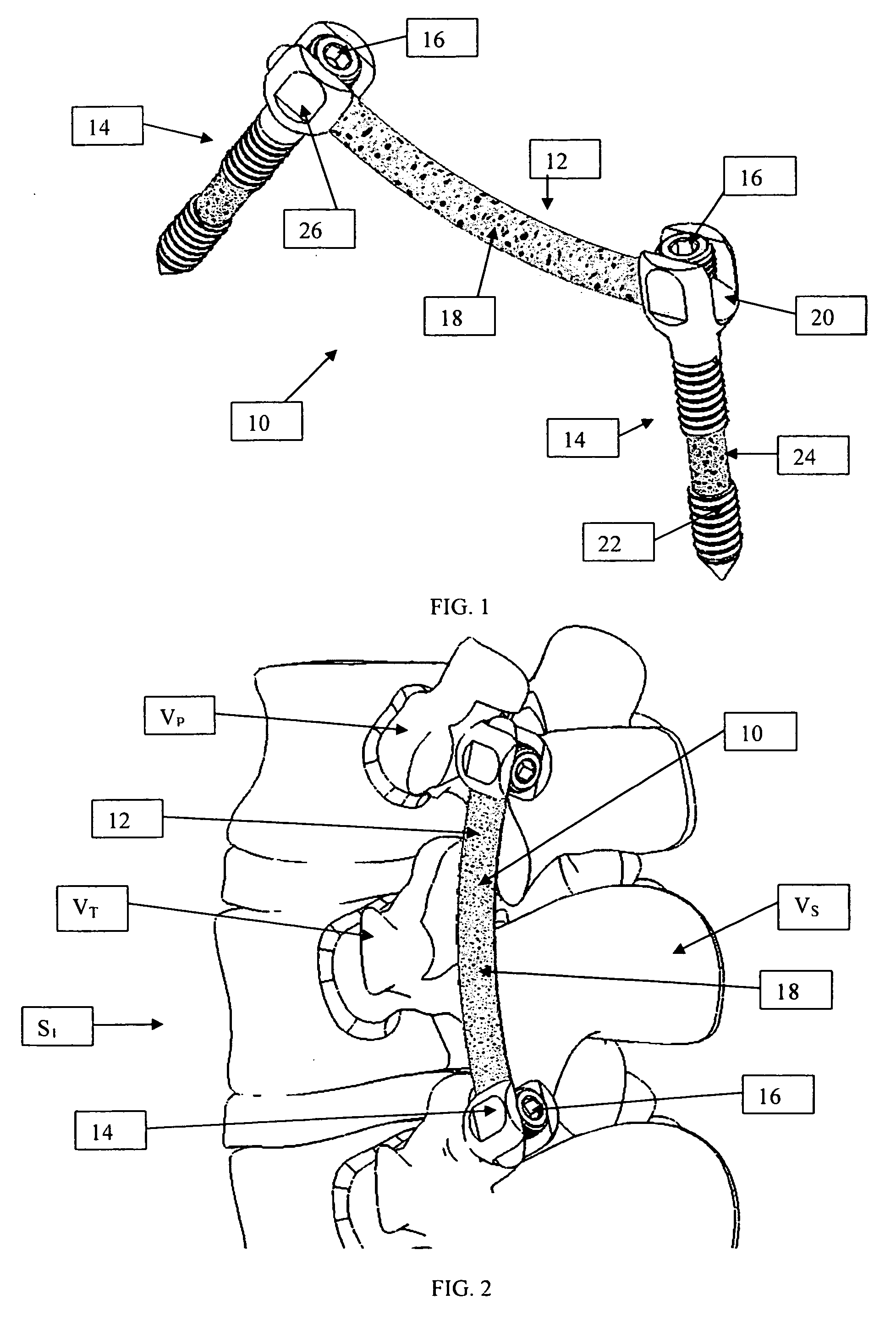
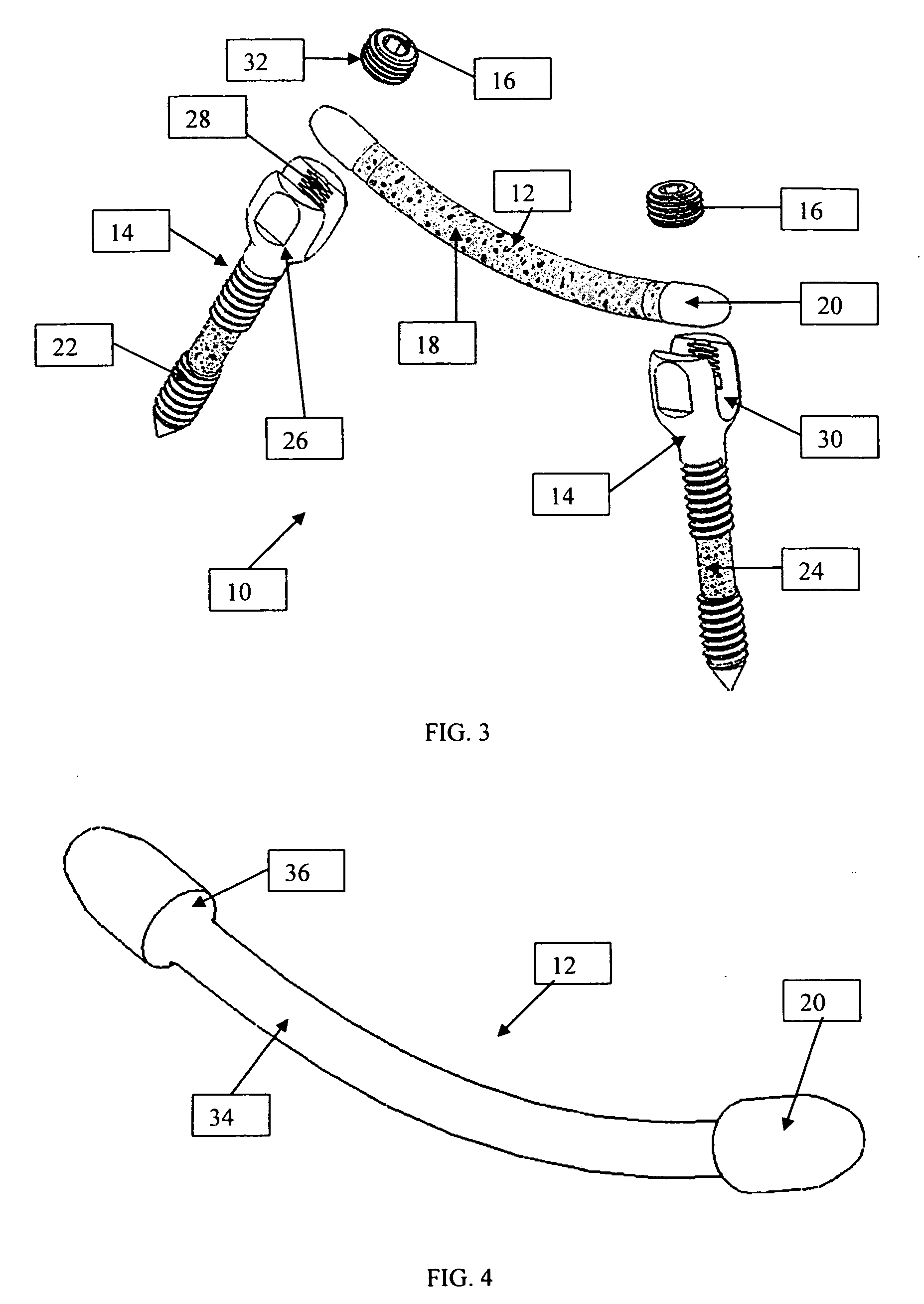
[0036] As shown in the exemplary drawings, an osteoconductive spinal fixation device referred to generally in FIGS. 1-3 by the reference numeral 10 is provided for attachment to at least a pair of adjacent patient bones such as spinal vertebrae S1 (FIG. 2) to maintain the skeletal structures in spaced relation while promoting bone ingrowth and fusion. In general, the improved fixation device 10 comprises a bio-compatible support structure such as the illustrative rod 12 having a dense substrate 34 (FIG. 4) providing a strong mechanical load bearing structure and a porous construction 18 to define an open lattice conducive to bone ingrowth and fusion. The preferred embodiment is manufactured from a high strength ceramic material, allowing for load carrying abilities, as well as substantial radiolucency and non-magnetic characteristics. This open-celled construction 18 is coated internally and externally with a biologic coating selected for relatively high osteoconductive and bio-acti...


PUM

PropertyMeasurementUnit
pore sizeaaaaaaaaaa
pore sizesaaaaaaaaaa

Abstract

An improved spinal fixation system is provided for human implantation, including a set of screws with interconnecting rods for implantation into the pedicle and between two adjacent vertebrae or a plate with screws for fixating two adjacent vertebrae. The screws, rods, and plates include a substrate portion of high strength biocompatible material and a controlled porosity analogous to natural bone. The substrate portion may be coated with a bio-active surface coating material such as hydroxyapatite or a calcium phosphate to promote bone ingrowth and enhanced bone fusion. Upon implantation, the fixation system provides a desired combination of mechanical strength together with osteoconductivity and bio-activity to promote bone ingrowth and fusion, as well as radiolucency for facilitated post-operative monitoring. The fixation system may additionally carry one or more natural or synthetic therapeutic agents for further promoting bone ingrowth and fusion.

Description

BACKGROUND OF THE INVENTION [0001] The spinal column is a highly complex system of bones and connective tissues that provides support for the body and protects the delicate spinal column and nerves. The spinal column includes a series of vertebrae stacked one atop the other, whereby each vertebral body includes a relatively strong bone portion forming the outside surface of the body (cortical) and a relatively weak bone portion forming the center of the body (cancellous). Situated between each vertebral body is an intervertebral disc that provides for cushioning and dampening of compressive forces applied to the spinal column. The vertebral canal containing the delicate spinal cords and nerves is located just posterior to the vertebral bodies. [0002] Various types of spinal column disorders are known and include scoliosis (abnormal lateral curvature of the spine), kyphosis (abnormal forward curvature of the spine, usually in the thoracic spine), excess lordosis (abnormal backward cu...

Claims


Application Information

Patent Timeline
Patent Type & Authority Applications(United States)
IPC IPC(8): A61F2/30
CPCA61B17/7005A61B17/7011A61B17/7037A61B17/7059A61F2310/00796A61B17/866A61B2017/00004A61F2/0077A61F2310/00592A61B17/863A61B17/7032
Inventor BERRY, BRET M.KHANDKAR, ASHOK C.LAKSHMINARAYANAN, RAMASWAMY
Owner AMEDICA A DELAWARE
Why Eureka
Try Eureka