Electromagnetic actuator having an armature coil surrounded by heat-conducting anisotropy material and exposure apparatus

Inactive Publication Date: 2005-01-25
CANON KK
View PDF45 Cites 27 Cited by
  • Summary
  • Abstract
  • Description
  • Claims
  • Application Information

AI Technical Summary

Benefits of technology

It is an object of the present invention to provide an electromagnetic actuator, such as a linear motor or the like,

Problems solved by technology

Accordingly, the driving force defined by (the mass of a moving body)×(acceleration) becomes very large, resulting in an increase in the calorific value of a linear motor for driving a stage, and the influence of generated heat from the motor on its surroundings is causing a problem.
However, since the volume cannot be increased due to a limitation in design, and there is a limitation in the magnetic flux density due to the physical properties of the magnetic material, the current of the armature coil must be increased.
In the above-described conventional linear motors, since heat generated at the armature coil is not completely transmitted to the refrige

Method used


Image

  • Electromagnetic actuator having an armature coil surrounded by heat-conducting anisotropy material and exposure apparatus
  • Electromagnetic actuator having an armature coil surrounded by heat-conducting anisotropy material and exposure apparatus
  • Electromagnetic actuator having an armature coil surrounded by heat-conducting anisotropy material and exposure apparatus

Examples


first embodiment

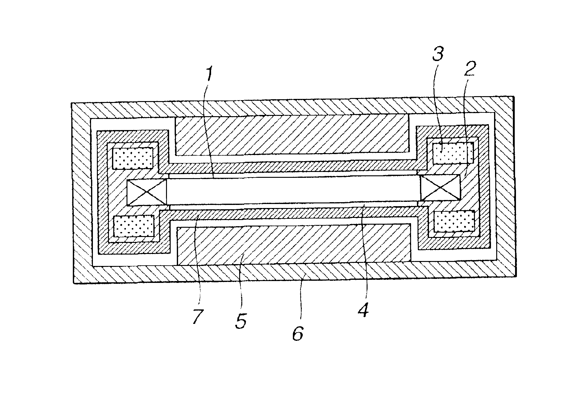
FIGS. 1 and 4 show the first embodiment. FIG. 1 is a schematic cross-sectional view illustrating a linear motor, obtained by cutting the linear motor at a plane vertical to the direction of movement, according to a first embodiment of the present invention.

In FIG. 1, a coil 1 serves as an armature of the linear motor. A supporting member 2 supports the armature coil 1. A refrigerant 3 flows within the supporting member 2. A filler 4 covers the surface of the armature coil 1. A permanent magnet 5 generates a magnetic field for the linear motor. A yoke 6 provides a magnetic circuit with the magnetic field generated by the permanent magnet 5 and the armature coil 1. A material having heat-conduction anisotropy 7 comprises a graphite sheet or the like. The supporting member 2 comprises a pair of bar-shaped members extending in the direction of movement and fixed parallel to each other, and supports the armature coil 1 between the pair of bar-shaped members.

The operation of the linear mo...

second embodiment

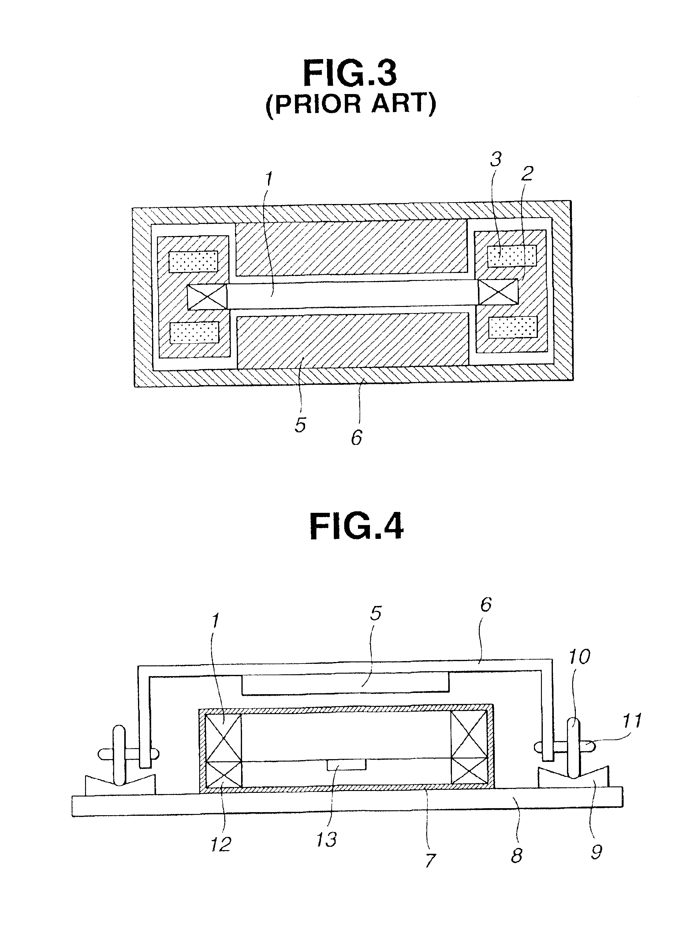
FIG. 4 is a schematic cross-sectional view illustrating a moving-magnet-type linear motor, obtained by cutting the linear motor at a plane vertical to the direction of movement, according to a second embodiment of the present invention. As shown in FIG. 4, in the linear motor of the second embodiment, an armature coil 1 and a rail 9 are fixed on a surface plate 8, and a yoke 6 mounting a permanent magnet 5 moves on the surface plate 8 in directions perpendicular to the plane of FIG. 4. Rollers 10 are rotatably supported on respective shafts 11 at both sides of the yoke 6 with respect to the direction of movement, whereby the yoke 6 performs rectilinear movement on the rail 9. A magneto-electric transducer 13 for position detection and a magneto coil 12 for speed control are provided on the surface plate 8. By movement of the permanent magnet 5, a voltage is generated in the magneto coil 12. The speed of the linear motor is controlled by inputting this voltage to a control circuit.

In...

third embodiment

A linear motor according to a third embodiment of the present invention is the same as the linear motor of the second embodiment, except that a mechanism for optically detecting the speed is provided instead of the magneto coil 12.

FIG. 5 is a schematic cross-sectional view illustrating a moving-magnet-type linear motor, obtained by cutting the linear motor at a plane vertical to the direction of movement, according to a third embodiment of the present invention. In FIG. 5, there are shown inclined reflecting surfaces 14 and 15. Light from a light-emitting device (not shown) fixed on a surface plate 8 is reflected at the inclined reflecting surface 14, and is then guided to the inclined reflecting surface 15 via a slit provided in a main scale 16. The light is then reflected at the inclined reflecting surface 15, and is then guided to a photosensor (not shown) fixed on the surface plate 8 together with the light-emitting device. The main scale 16 is a strip member extending parallel ...


PUM


Abstract

An electromagnetic actuator has a permanent magnet and an armature coil that performs relative movement with respect to the permanent magnet. A material having heat conduction anisotropy surrounds a surface of the armature coil and a heat radiating member radiates heat generated by the armature coil. The heat conduction anisotropic material is oriented to guide the heat generated from the armature coil to the heat radiating member. The actuator may be used in one or more groups of semiconductor substrate exposure apparatuses in a manufacturing factory that performs plural processes using the group of manufacturing apparatuses.

Description

BACKGROUND OF THE INVENTION1. Field of the InventionThe present invention relates to an electromagnetic actuator, such as a linear motor or the like, including a stator and a movable element, an exposure apparatus including the electromagnetic actuator, a device manufacturing method using the exposure apparatus, a device manufacturing factory in which the exposure apparatus is installed, and a method for performing maintenance of the exposure apparatus.2. Description of the Related ArtTypical conventional exposure apparatuses used for manufacturing various devices, such as semiconductor devices, are step-and-repeat-type exposure apparatuses (also called “steppers”) which sequentially expose a plurality of exposure regions on a substrate (a wafer or a glass substrate) with a pattern of an original plate (a reticle or a mask) via a projection optical system while moving the substrate stepwise, and step-and-scan-type exposure apparatuses (also called “scanners”) which repeat exposure a...

Claims


Application Information

Patent Timeline
IPC IPC(8): H02K41/03H02K9/22H02K9/19H02K33/18H02K41/02
CPCG03F7/70758H02K41/03H02K9/22G03F7/70858H02K9/227H02K9/223
Inventor UKAJI, TAKAO
Owner CANON KK
Why Eureka
Try Eureka