For a given
potential difference between two spaced apart conductors, the amount of leakage current that will flow between them will vary depending upon the volume resistivity of the insulating material that separates the conductors, that is, if a relatively lower-resistance insulator is used, this will result in a relatively higher leakage current.
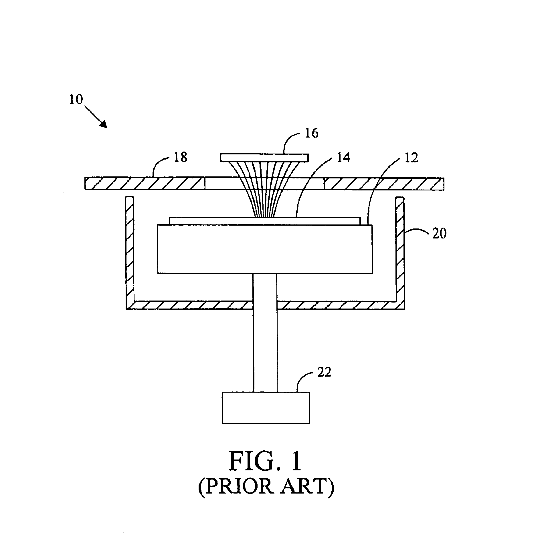
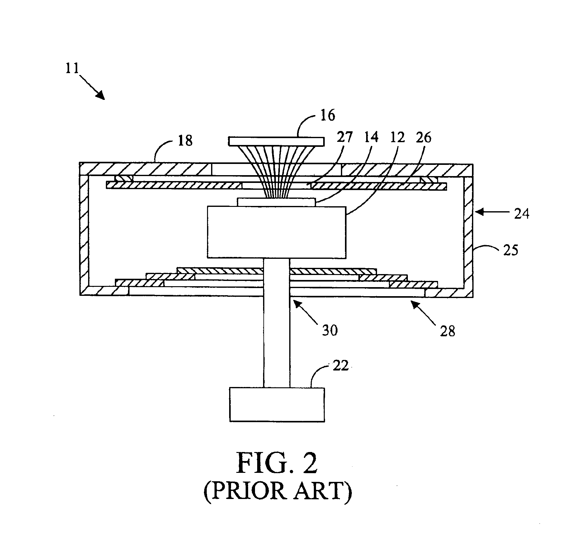
It has been found, however, that even with the use of guarded cables and
ceramic probing devices of the type just described, the level of undesired
background current is still not sufficiently reduced as to match the capabilities of the latest generation of commercially available test instruments, which instruments are able to monitor currents down to one femtoamp or less.
However, the
ceramic material used in these newer designs is relatively more expensive than the glass-
epoxy material it replaces.
Another problem with
ceramic materials is that they are relatively susceptible to the absorption of surface contaminants such as can be deposited by the
skin during handling of the
probe card.
These contaminants can decrease the
surface resistivity of the ceramic material to a sufficient extent as to produce a substantial increase in leakage current levels.
In addition, the more extensive and elaborate guarding structures that are used in these newer designs has contributed to a large increase in design and
assembly costs.
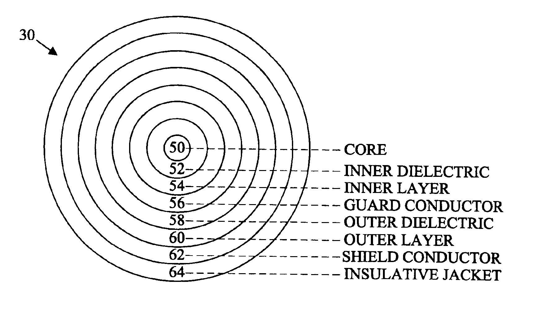
In a guarded
coaxial cable, triboelectric currents can arise between the guard conductor and the inner dielectric due to friction there between which causes free electrons to rub off the conductor and creates a charge buildup resulting in current flow.
For example, unless
special care is taken in assembling the
probe card, it is possible for surface contaminants, such as oils and salts from the
skin or residues left by solder flux, to contaminate the surface of the card and to degrade its performance (due to their ionic character, such contaminants can produce undesirable electrochemical effects).
Furthermore, even assuming that the card is designed and assembled properly, the card may not be suitably connected to the test instrument or the instrument may not be properly calibrated so as to completely null out, for example, the effects of
voltage and current offsets.
Due to these factors and others, when a new
probe card design is being tested, it can be extremely difficult to isolate the causes of undesirable
background current in the new design due to the numerous and possibly interacting factors that may be responsible.
In addition, thermal chucks may include fluid paths, such as tubular cavities, within the chuck that carry hot or cold fluids that likewise result in
noise in the
signal path.
Furthermore, thermal chucks are constructed of a variety of different materials, such as different
conductive materials and different dielectric materials, all of which expand and contract at different rates further exasperating the potential of undesired
noise in the test
signal.
Moreover, different temperatures change the
relative humidity in the probe
station, which in turn, change the amount of
moisture absorbed by the dielectric materials, which in turn, change the impedance of the materials therein, and thus may result in variable leakage currents in the test
signal.
Furthermore, vibrations of the probe
station itself, and thus the chuck located therein, as a result of testing, as a result of the external environment, and as a result of the air flowing within the probe
station likewise induces undesirable leakage currents and
noise in the signal path.
As it may be observed, due to these and other factors, when a new chuck design is being tested, it can be extremely difficult to isolate the causes of undesirable
background current in the new design due to the numerous and possibly interacting factors that may be responsible.
The vibrations of the probe station, the vibrations from air blowing across the cables, the vibrations of the cables after moving the chuck, the vibrations from
stepper motors connected to the chuck, the vibrations from flowing
coolant in the hoses of the service loops, etc., all potentially results in undesirable currents in the signal path.
In addition, magnetic and
capacitive coupling between the power and ground conductors to the signal conductor likewise results in undesirable currents in the signal path.
Further, the service loop itself is normally constructed of
metal or otherwise includes
metal bands, which likewise radiates electromagnetic signals that may result in undesirable currents in the signal path.
As it may be observed, due to these factors, when a service
loop design is being tested, it can be extremely difficult to isolate the causes of undesirable background current in the new design due to the numerous and possibly interacting factors that may be responsible.
As an initial matter, the lid of the
enclosure may have vibrational mechanical motion which results in a change in
capacitance between the lid and the chuck, and a probe supported by the lid and the chuck, thus causing some undesirable currents in the signal path, in accordance with movement of the lid.
In addition, there may be electrical
surface charges on interior surfaces of the probe station, and other components contained therein, which also result in potentially undesirable currents in the signal path.
Other structures within the
enclosure can likewise result in undesirable currents in the signal path, such as for example, sliding plates below the chuck, conductive coated baffles below the chuck, air flow within the enclosure, motors for moving the chuck, position sensors, sensor wires, and
dew meters.
In addition to those items contained within the enclosure of the probe station, there are additional sources of potential noise in the signal path located near the enclosure.
As it may be observed, due to these and other factors, when a probe station itself is being tested, it can be extremely difficult to isolate the causes of undesirable background current in the new design due to the numerous and possibly interacting factors that may be responsible.
As it may be observed, due to interrelated factors related to the chuck, the probing device, the probe card, the service loop, and other aspects of the probe station, when, the entire probe station itself is being tested, it can be extremely difficult to isolate the causes of undesirable background current in the new design due to the numerous and possibly interacting factors that may be responsible.
Accordingly, with each design and with increasingly lower noise requirements, it is exceedingly difficult to determine the
primary source of the noise in the signal path.

