Time synchronizing system

a time synchronization and time technology, applied in the field of time synchronization system, can solve the problems of loss of continuity of time, decline of economical value, and decrease in data transmission efficiency, and achieve the effect of good economical characteristic and high accuracy

Inactive Publication Date: 2005-01-25
KK TOSHIBA
View PDF11 Cites 32 Cited by
  • Summary
  • Abstract
  • Description
  • Claims
  • Application Information

AI Technical Summary

Benefits of technology

It is a primary object of the present invention, which was devised to obviate the problems given above, to provide a time synchronizing system capable of ensur

Problems solved by technology

This might induce a decrease in data transmission efficiency, and a decline of economical value, and might lose a continuity of time bec

Method used


Image

  • Time synchronizing system
  • Time synchronizing system
  • Time synchronizing system

Examples


Embodiment Construction

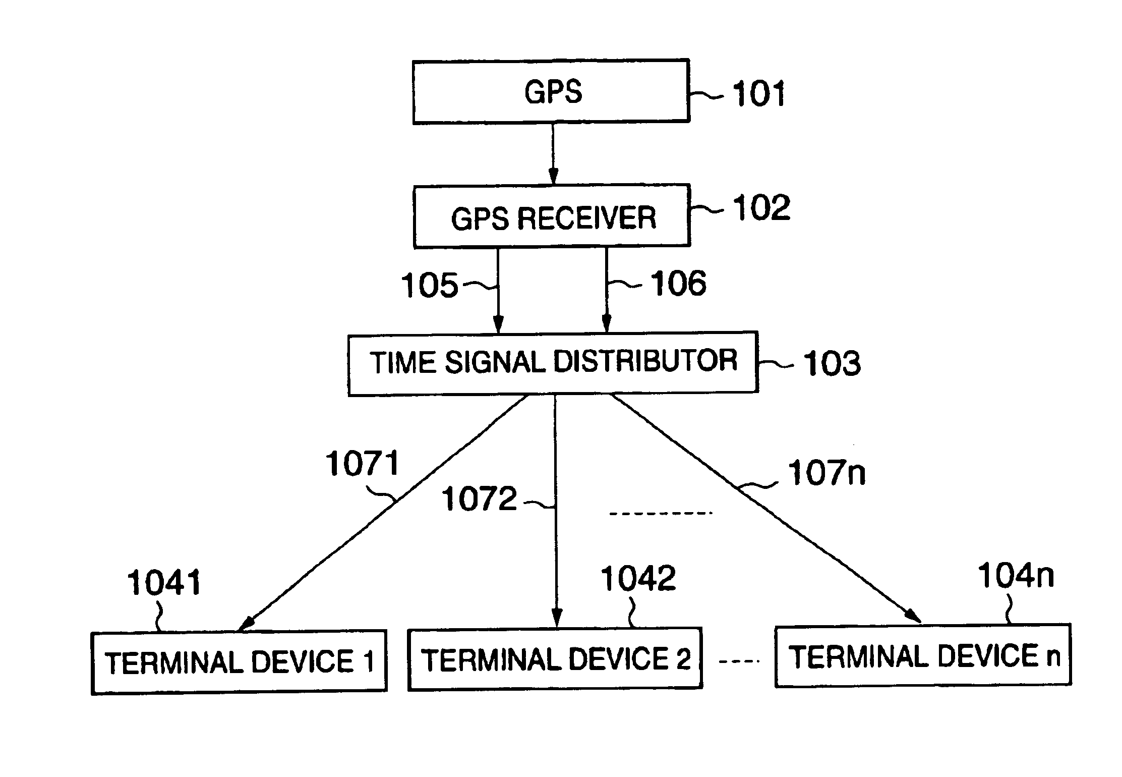
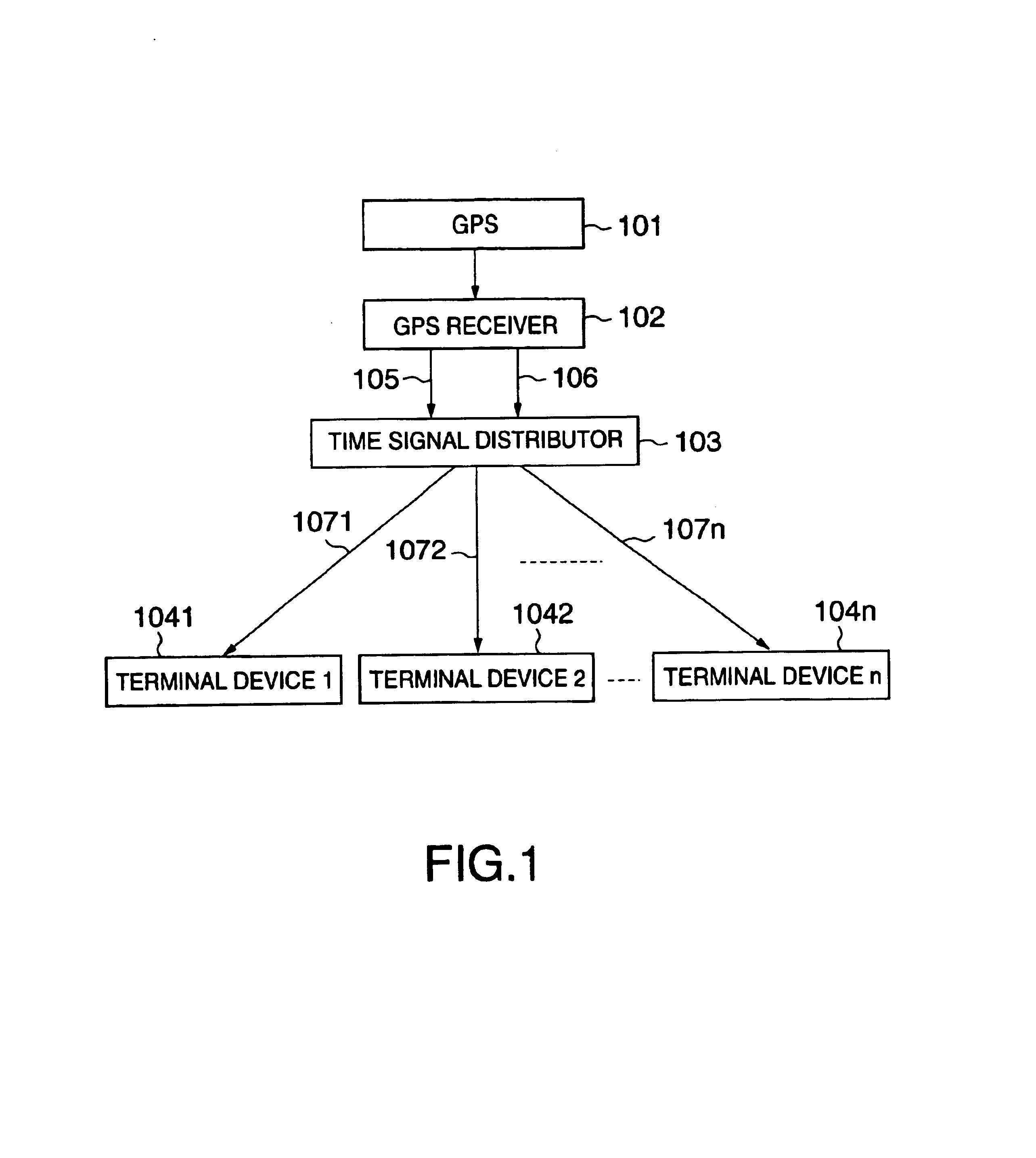
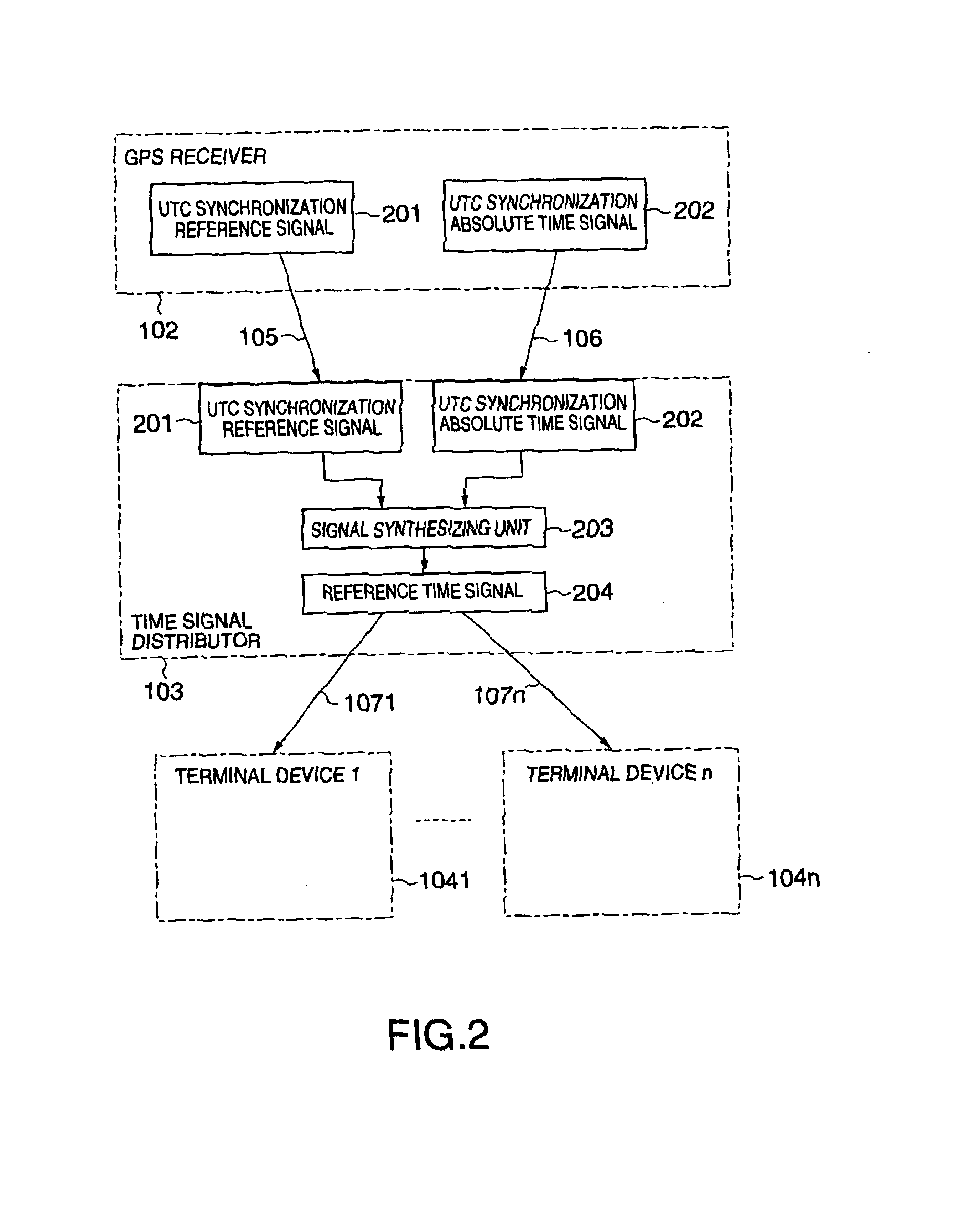
FIG. 1 is a diagram showing a whole architecture of a time synchronizing system according to the present invention. The system shown in FIG. 1 is constructed of a GPS (Global Positioning System) 101, a GPS receiver 102, a time signal distributor 103 and a plurality of distributed control oriented terminal devices 1041-104n. Herein, terminal devices 1041-104n are defined as terminal devices for executing the distributed control of, e.g., a plant. The GPS receiver 102 receives a UTC synchronization reference signal and a UTC synchronization absolute time signal from the GPS 101. Then, the GPS receiver 102 transmits, to the time signal distributor 103, the UTC synchronization reference signal via a pulse signal line 105 and the UTC synchronization absolute time signal via a serial signal line 106. The pulse signal line 105 is composed of, e.g., a coaxial cable. The time signal distributor 103 transmits reference time signals to the plurality of terminal devices 1041, 1042, . . . , 104n...


PUM


Abstract

A time synchronization system comprises a GPS (Global Positioning System) receiver for receiving a time signal from a Global Positioning System (GPS), and outputting a UTC (Universal Time Coordinated) synchronization reference signal synchronizing with UTC and a UTC synchronization absolute time signal, and a time signal distributor for generating a reference time signal synchronizing with UTC from the synchronization reference signal and the absolute time signal, and transmits this reference time signal in distribution to a plurality of distributed control oriented terminal devices. The time synchronization between the plurality of distributed control oriented terminal devices can be thereby taken.

Description

BACKGROUND OF THE INVENTION1. Field of the InventionThe present invention relates to a time synchronizing system for unifying the time between a plurality of distributed control oriented terminal devices.2. Related Background ArtGenerally, what is dominant among a variety of plant monitor control systems is a distributed control system that includes, with developments of a microcomputer and a signal transmission technology, a plurality of terminal devices connected to each other via transmission lines. Further, in this type of monitor control system, an occurrence time data when a state change is added to various categories of input data given from the plant and recorded, and the state is thus displayed.When the plant data received from the plant are transmitted to other terminal device via the transmission line from one terminal device, it is required that the time data be added.In the terminal device receiving first the input data, a time signal is added in a state variation of th...

Claims


Application Information

Patent Timeline
IPC IPC(8): G04G5/00G04G7/00G01S19/05G01S19/09G01S19/11G01S19/14G01S19/46G04R20/00G04R20/02G04R20/26G04R40/06H04B7/155H04L7/00
CPCG04G5/002G04R40/06G04R20/02G04G7/00H04B7/155
Inventor TORIKOSHI, HIDEKIMORITA, SHIGEKAZUHAMAMATSU, KOICHISHUTO, ITSUO
Owner KK TOSHIBA
Why Eureka
Try Eureka