Method of adhesive bonding by induction heating

a technology of induction heating and adhesive bonding, which is applied in the direction of electric heating, electric/magnetic/electromagnetic heating, manufacturing tools, etc., can solve the problems of labor cost, assembly time, labor cost, etc., and achieve the effect of melting more quickly

Inactive Publication Date: 2005-02-01
OMG INC
View PDF209 Cites 61 Cited by
  • Summary
  • Abstract
  • Description
  • Claims
  • Application Information

AI Technical Summary

Benefits of technology

Accordingly, it is an advantage of the present invention to provide an inductive heating apparatus having a work coil that is driven by an electrical current, in which an electrical current at a power converter stage is increased to a predetermined magnitude, whereupon the voltage magnitude is measured and used to determine a “distance value” that substantially represents the actual distance between the work coil and a susceptor, then based upon that distance value, the current and voltage magnitudes are adjusted so as to cause said work coil to emit a magnetic field at a predetermined desired power level that will induce eddy currents in the susceptor's electrical conductor to cause a temperature rise.
to provide an inductive heating apparatus having a work coil that is driven by an electrical current, in which an electrical current at a power converter stage is increased to a predetermined magnitude, whereupon the voltage magnitude is measured and used to determine a “distance value” that substantially represents the actual distance between the work coil and a susceptor, then based upon that distance value, the current and voltage magnitudes are adjusted so as to cause said work coil to emit a magnetic field at a predetermined desired power level that will induce eddy currents in the susceptor's electrical conductor to cause a temperature rise.
It is another advantage of the present invention to provide an inductive heating apparatus having a work coil that is driven by an electrical current, in which both a current magnitude and a voltage magnitude of a power converter stage are sampled over multiple sampling time intervals, and the average current and voltage magnitudes are used to calculate a power level being generated, and the power level is then adjusted according to a profiled energy delivery scheme until achieving a predetermined accumulated energy for the profiled energy delivery scheme, which ends the power cycle.
It is a further advantage of the present invention to provide a susceptor apparatus consisting of a strip-like structure having a length, width, and thickness, in which the structure includes at least one layer of an electrically conductive material and at least one layer of an adhesive material proximal to at least one of its outer surfaces, wherein the electrically conductive material generates an eddy current when exposed to a magnetic field of a predetermined minimum intensity, and the layer of electrically conductive material exhibits a thickness in the range of 0.10 through 3 mils.
It is yet another advantage of the present invention to provide a susceptor apparatus consisting of a strip-like structure having a length, width, and thickness, in which the structure includes at least one layer of an electrically conductive material and at least one layer of an adhesive material proximal to at least one of its outer surfaces, wherein the electrically conductive material generates an eddy current when exposed to a magnetic field of a predetermined minimum intensity, and the at least one layer of an electrically conductive material comprises at least two individual layers of electrically conductive material, in which each of the electrically conductive layers is separated from one another by an insulative layer.
It is still another advantage of the present invention to provide a susceptor apparatus consisting of a strip-like structure having a length, width, and thickness, in which the structure includes at least one layer of an electrically conductive material and at least one layer of an adhesive material proximal to at least one of its outer surfaces, wherein the electrically conductive material generates an eddy current when exposed to a magnetic field of a predetermined minimum intensity, and the structure contains at least one fusible portion that melts more quickly than other portions of said structure when its temperature is raised.

Problems solved by technology

Historically, bonding materials quickly without use of mechanical fasteners has been quite difficult.
Some of the problem areas which exist include: assembly time, cost of materials and labor, quality of the bond between component structures being assembled, reliability of the process of assembly, the typical requirement of fairly difficult finishing steps, convenience (or lack thereof) of use for the end-users, worker safety issues, and the difficulty in maintaining a good quality of appearance of the finished goods.
These were major disruptive technologies that have evolved over the last 45 years and which have slowly grown the fastening market and have significantly replaced traditional mechanical fasteners in many markets.
Adhesive bonding is generally superior to mechanical fastening, but present technology doesn't allow for cost-effective pre-positioning and rapid development of a strong bond on demand with one step.
No current adhesive system allows for pre-positioning coupled with instantaneous bonding.
Most of today's adhesives are slow to cure, requiring minutes to hours, thus requiring clamping and other direct personal attention by the installer.
It should be noted that UV-curable adhesives involve chemical handling and are not currently reversible.
(1) Many product assembly sites are often dirty and difficult to keep clean.
Certain adhesive systems cannot handle such situations.
(4) The ability to directly heat many product components to cure adhesives is extremely limited, particularly as many plastic components can melt, and wood-based or cellulose-based millwork can burn.
These adhesives allow for an extremely rapid adhesive setting, but cannot in any way be pre-positioned before placement as the adhesive cures during positioning.
These adhesives are generally the most expensive adhesives.
Furthermore, they are difficult to handle, and have a limited shelf life.
Finally, there is no way to easily reverse cyanoacrylate, or super glue, bonds.
Like super glues, such products allow for extremely rapid adhesive bonding, but again, are extremely limited with regard to pre-positioning and, as with the “superglues,” again, there is no room for error.
Furthermore, pressure-sensitive adhesives are limited in their ultimate strengths unless they are thermosetting.
In the case of a thermosetting PSA, some form of heat- or moisture-activation is required which is generally impractical for non-heat-resistant products, or where humidity controls are unavailable.
The latter two above thermosetting processes are time intensive.
Even more importantly, pressure sensitive adhesives can be applied only in very narrow temperature ranges, typically from 55° F. to 90° F. Furthermore, above 90° F., many common PSA's weaken dramatically.
As a further note on PSA's, they are incapable of flow without heat to accommodate uneven surfaces, and if exposed to dust or other particulates, they immediately lose much of their potential adhesive strength.
Finally, it is extremely difficult, if not impossible in most cases, to disassemble parts that use PSA's.
The cost of PSA's can range from being some of the most inexpensive to some of the most expensive adhesives available today.
Such limitations are the reasons that hot melt adhesives are used most extensively in the packaging industry and also for bonding small parts or surface areas.
Furthermore, such adhesives cannot be reheated after product assembly without significantly or entirely heating the product assembly.
Furthermore, most hot melt adhesives are moderate to low in cost, especially when compared to the super glues or the light-curable adhesives.
Epoxies are not difficult to handle, but do require special care as exposure can sometimes be detrimental to human health (causing skin irritations and burning).
A major problem with two-part epoxies is that cure time can vary dramatically with temperature.
In fact, some systems cure so rapidly at temperatures above 90° F. that they become almost unusable.
Epoxy bonds cannot be easily reversed.
Two-part systems are the most common and generally take minutes to hours to cure.
Both systems have the problem that one component of the two, the isocyanate, is moisture-sensitive.
If water gets into the adhesive, or if the humidity is too high, the isocyanate will react with the water, generate a gas, and cause foaming to occur.
Even worse, if the moisture gets into a container unbeknownst to the user, and the container is then closed, the container can explode.
As a result, two-component and moisture-cure urethanes are generally only used by skilled or specially trained personnel.
Furthermore, because of their reactive nature and environmental susceptibility, most urethane adhesive systems require specialized mixing and dispensing equipment that must be cleaned on a frequent basis.
Furthermore, this technology generally employs high pressures to facilitate bond formation.
Distributions of these electrical currents and the heat they produce are not uniform in a conductive medium, such as a susceptor, exposed to an alternating magnetic field.
Of course, for aircraft structures, high strength bonds can be critical.
Such devices are not particularly useful in “quick” bonding of substrates.
Previous induction heating devices suffer from an inability to be made truly portable, i.e., lightweight, while simultaneously delivering the energy necessary to form bonds in short periods of time.

Method used


Image

  • Method of adhesive bonding by induction heating
  • Method of adhesive bonding by induction heating
  • Method of adhesive bonding by induction heating

Examples


first embodiment

FIG. 8A is a block diagram 300 of the major electrical components of the first embodiment induction heating tool 10 of the present invention. Starting with a power source of 117 VAC (also sometimes referred to herein as a 120 VAC alternating current source) at 302, the line power is connected to a fuse at 304, then an ON-OFF switch at 306, and a thermistor at 308. This line voltage then drives into a transformer 316 and also into a 160 VDC power supply 314.

The heating induction tool 10 of the present invention can also be battery operated, and in that circumstance there would be no 117 VAC (or 120 VAC) source. Instead, a battery 310 is utilized, which provides direct current into an inverter stage at 312 (see FIG. 7, for example). This becomes the power source for the 160 VDC power supply 314. Either the battery 310 or the transformer 316 provides power for a +5 VDC power supply 318. This +5 volt supply provides power to a microprocessor stage 350.

The output of the 160 VDC power sup...

second embodiment

Referring now to FIG. 8B, a block diagram 301 is provided illustrating some of the major electrical components of the second embodiment hand held induction heating tool 10. An AC power source, such as 120 VAC line voltage, is provided to supply power to a rectifier and filter stage at 370. A DC-DC pre-regulator 372 receives direct current from the output of the rectifier / filter stage 370, and a DC-AC inverter 374 receives a controlled voltage level from the pre-regulator 372. The output of the inverter 374 is used to drive an induction head 376, which is essentially the same as the head sub-assembly 50 depicted on FIGS. 1 and 2.

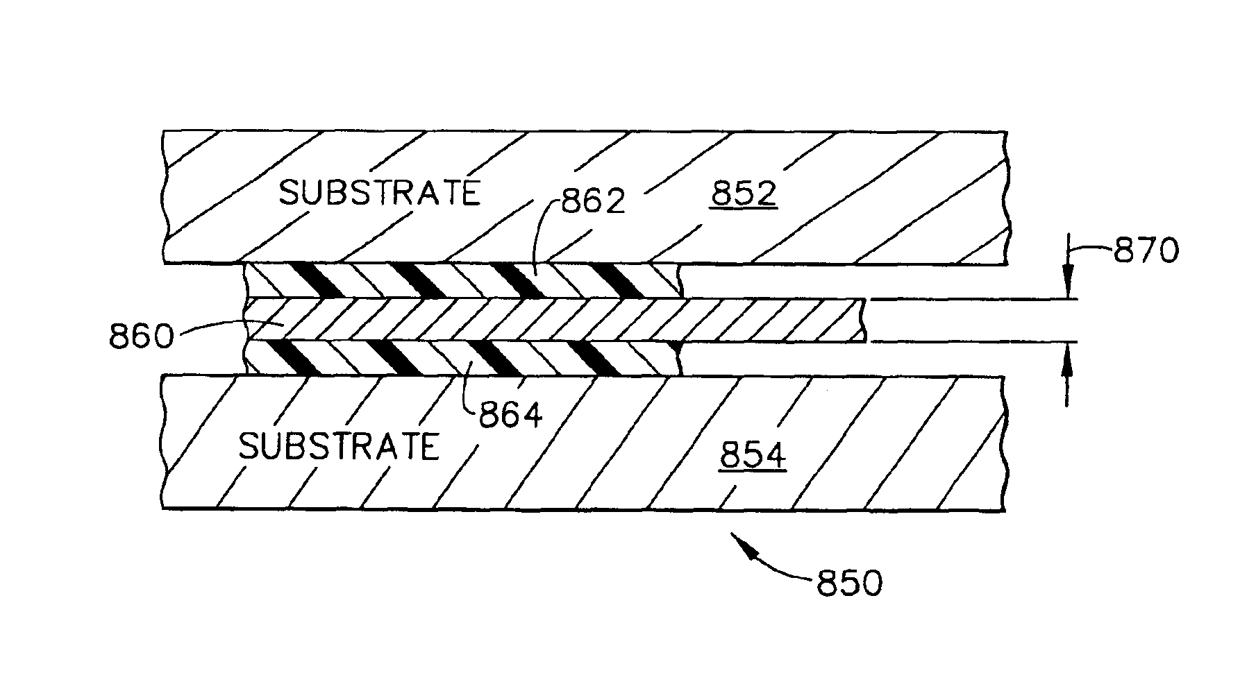
The induction head 376 generates a magnetic field via a work coil (not shown on FIG. 8B, but which is part of the induction head), and this magnetic field is directed toward an aluminum susceptor 390 which includes at least one relatively thin “foil” layer of electrically conductive aluminum (but which could easily use a different material for its electricall...


PUM

PropertyMeasurementUnit
thicknessaaaaaaaaaa
thicknessaaaaaaaaaa
thicknessaaaaaaaaaa

Abstract

A method for using magnetic fields to heat magnetically susceptible materials within and / or adjacent to adhesives, so as to bond, bind, or fasten solid materials to one another. The system uses alternating magnetic fields that induce eddy currents and generate heat within susceptors. An induction heating tool is used to emit the magnetic field at its work coil, and an electronic controller measures the energy being used by a power converter that generates the alternating current driving the work coil which creates the magnetic field. The heating tool is used in a method of adhesive bonding in which the thickness of the conductive layer of the susceptor is in the range of 0.01-3.0 mils, or the heating event time interval is in the range of 0.05-10.0 seconds, or the average power density of the magnetic field at the susceptor is in the range of 10-5000 Watts per square inch.

Description

TECHNICAL FIELDThe present invention relates generally to induction heating equipment and is particularly directed to a hand held induction tool of the type which produces a magnetic field in a predetermined direction. The invention is specifically disclosed as an induction heating tool that induces eddy currents in thin foil susceptors to raise the temperature of the susceptors to melt or soften an adhesive coating on the susceptor's surface, for bonding trim to wallboard.BACKGROUND OF THE INVENTIONHistorically, bonding materials quickly without use of mechanical fasteners has been quite difficult. Some of the problem areas which exist include: assembly time, cost of materials and labor, quality of the bond between component structures being assembled, reliability of the process of assembly, the typical requirement of fairly difficult finishing steps, convenience (or lack thereof) of use for the end-users, worker safety issues, and the difficulty in maintaining a good quality of ap...

Claims


Application Information

Patent Timeline
Patent Type & Authority Patents(United States)
IPC IPC(8): B23K13/01B23K13/00H05B6/06H05B6/02H05B6/14
CPCB23K13/01
Inventor RIESS, EDWARD A.MALOFSKY, ADAM G.BARBER, JOHN P.BAUER, DAVID P.
Owner OMG INC
Why Eureka
Try Eureka